
LiF-coated doped and undoped yttrium oxide

a technology of yttrium oxide and powder, which is applied in the field of yttrium oxide powder, can solve the problems of unsuitable laser material or window, poor yield, and unreliable optical loss of articles, and achieve the effect of avoiding spalling

Active Publication Date: 2008-11-11
THE UNITED STATES OF AMERICA AS REPRESENTED BY THE SECRETARY OF THE NAVY
View PDF7 Cites 15 Cited by
  • Summary
  • Abstract
  • Description
  • Claims
  • Application Information

AI Technical Summary

Benefits of technology

[0007]Optionally, the particle is made by a process including mixing the yttria core with a solution of the fluoride salt in a solvent to form a slurry; and spraying the slurry into a drying column. The slurry enters the drying column as an aerosol under thermal conditions that avoid boiling the solvent. Thermal conditions in the drying column evaporate the solvent as the aerosol moves through the drying column to form a coating of the fluoride salt on the yttria core while substantially avoiding spalling.

Problems solved by technology

Traditional processing of polycrystalline yttria leads to high scattering and absorption losses that are distributed in localized yet random regions thus making the material unsuitable as either a laser material or a window.
Basically, the article does not posses uniform optical losses, and consequently the yield is poor, costs are high and large size and different shapes are not possible to manufacture.
However, advanced ceramics do not have these intrinsic sintering aids and must therefore be added.
However, due to the nature of particle-particle interactions, the mixture is far from homogeneous.
That level of homogeneity is several orders of magnitude too high to produce optical or laser quality polycrystalline material.
Inhomogeneity, for example, results in areas that have too much sintering aid and other areas that have little or no sintering aid.
While this is generally not too important in systems that are relatively easy to sinter or are not needed to be highly transparent, it is a major problem in the fabrication of transparent ceramics and laser quality polycrystalline materials.
This adds a tremendous amount of cost to the product since yields are low, and size is limited to small regions core drilled out of the large sample.

Method used


Image

  • LiF-coated doped and undoped yttrium oxide
  • LiF-coated doped and undoped yttrium oxide

Examples


example 1

Comparative

[0030]Traditional method Yb doped-yttria was made using a traditional process where 1.0 wt % LiF and 1 μm Yb-doped yttria particles (World Labo Nagoya, Japan) were mechanically mixed and then densified by hot pressing: ramp 20° C. / min to 950° C., hold 30 min., ramp 20° C. / min to 1200° C., hold 30 min and ramp 20° C. / min to 1650° C., hold 2 hours under vacuum and at 8000 psi pressure.

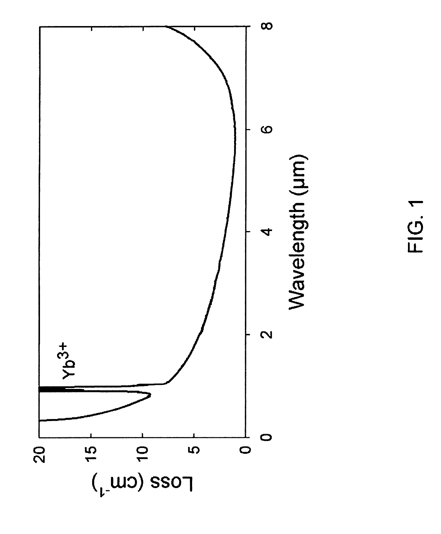
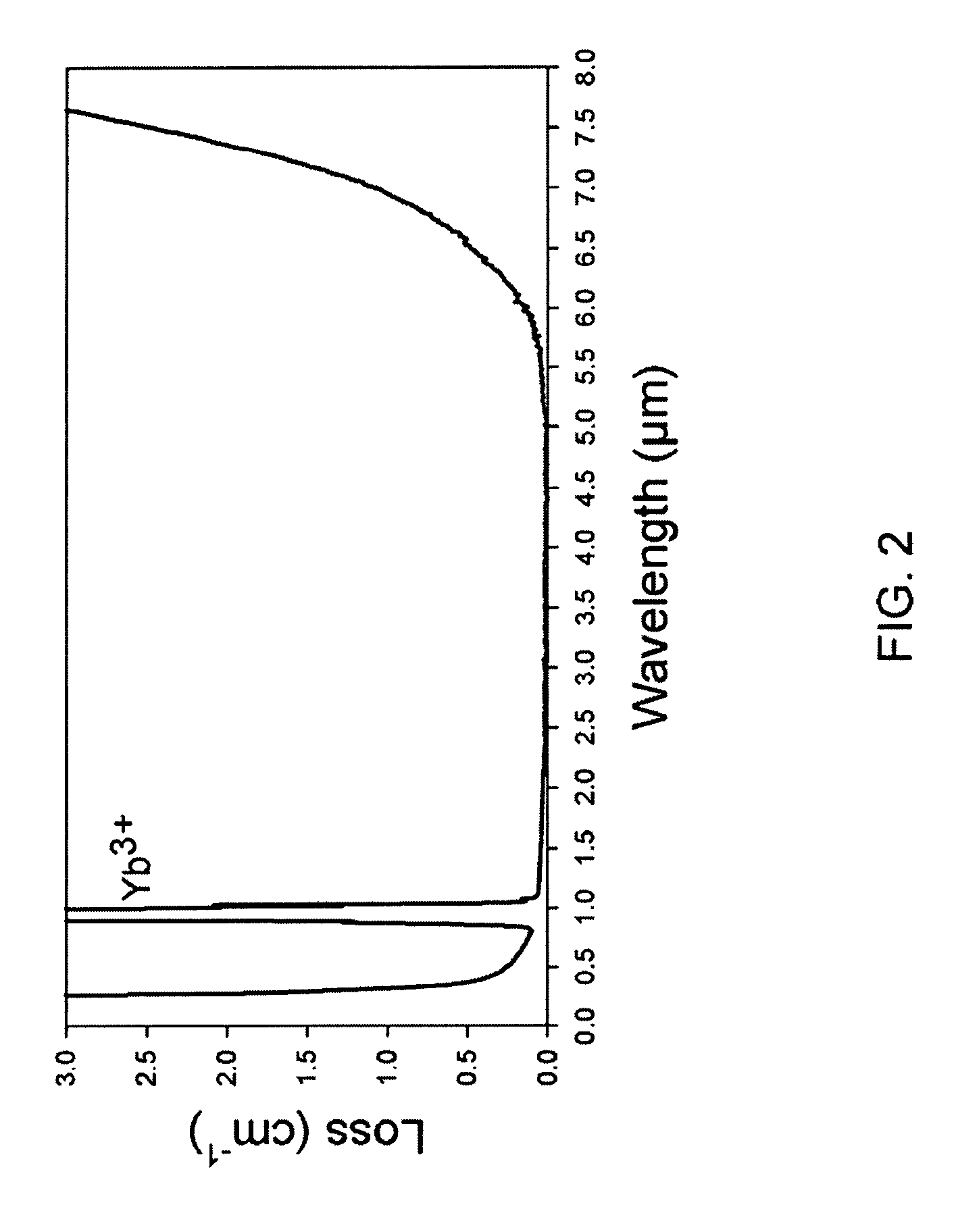
[0031]Loss plot (FIG. 1) shows loss of greater than 0.2 / cm. The loss varied with position on the sample surface and was random, limiting usefulness of sample.

example 2

[0032]LiF-coated Yb-doped yttria particle-LiF was dissolved in water (0.036 g LiF in 400 mL DI water) to make the stock solution. 600 mL of the stock solution was further diluted with 600 mL ethyl alcohol and then mixed with 15 g of Yb-doped yttria particles, and ultra-sonically sprayed. The column was 60 inches tall. The bottom of the ultrasonic spray head was about 6 inches from the top of the column. A 12 inch tall heater was wrapped around the column, centered at 27 inches from the top of the column. A second such heater was centered 47 inches from the top of the column. The heaters were set at 415° C. at the top heater and 430° C. at the bottom heater. Inside the column the temperatures were approximately about 30° C. at the bottom of the ultrasonic spray head, 150° C. at the center of the top heater and 270° C. at the center of the bottom heater, respectively. The LiF was specifically prevented from coming out of solution until it was falling through the spray-drying column. A...

example 3

[0034]Pressing into a transparent shape—The coated powder from Example 2 was placed in a flexible graphite-lined graphite hot press die. An example of flexible graphite consistent with the instant invention is Grafoil® flexible graphite by Sealing Devices, Inc. The die was placed in an argon / vacuum atmosphere hot press. Minimal pressure was applied until the powder started to densify at approximately 1100° C. and was then stepped up to or above 3000 psi when a temperature at or above 1450° C. was attained. The heating schedule was a 20° C. / min ramp to 950° C., a 30 minute hold to equilibrate the temperature profile, a 20° C. / min ramp to 1200° C., a 30 min hold to allow the now vaporized LiF to leave the hot press die, a 20° C. / min ramp to 1650° C., and a 2 hour hold to fully densify the powder into a transparent shape. The heating elements were turned off to allow natural cooling of the hot press and the hydraulic motor was turned off to allow the pressure to bleed off. The use of t...


PUM

PropertyMeasurementUnit
Temperatureaaaaaaaaaa

Abstract

An embodiment of the invention includes a particle. The particle includes a first yttria core; and a fluoride salt coating on the first yttria core. The coating is sufficiently continuous to prevent a large number of sites where a second yttria core may come into contact with the first yttria core. Optionally, the particle has been heated in an oxidizing atmosphere to a temperature in the range of about 400° C. to about 750° C. Optionally, the particle is substantially free of at least one of carbon-containing species and water. Optionally, the fluoride salt is lithium fluoride. Optionally, the fluoride salt is aluminum fluoride.

Description

FIELD OF THE INVENTION[0001]The invention is related to LiF-coated Yttrium oxide powders both doped and undoped.DESCRIPTION OF THE RELATED ART[0002]Dense yttrium oxide (Y2O3 or yttria) is hard, strong, possesses high thermal conductivity and is transparent from about 0.3-8 μm. Undoped yttria is useful as long wave infra red window, while rare earth doped yttria is useful as a high power laser material. Doping is the process of incorporating other atoms, in this case rare earth atoms (e.g. Yb, Nd, Er, etc.), into an otherwise pure matrix. Whereas most laser crystals are, as the name would imply, single crystals, coated powders are suitable for making polycrystalline material that behave as though they were single crystals. In this case, the coating is defined as being sufficiently adherent to the material and of such size and thickness as to prevent individual yttria surfaces form touching each other even after handling or submersing in a liquid or gas stream. From hereon, yttria wil...

Claims


Application Information

Patent Timeline
IPC IPC(8): B32B5/16
CPCB82Y30/00C04B35/62655C04B35/628C04B35/62886C04B35/62897C04B35/645C04B35/505Y10T428/2993C04B2235/3203C04B2235/3217C04B2235/3224C04B2235/445C04B2235/528C04B2235/5436C04B2235/5445C04B2235/5454C04B2235/662C04B2235/721C04B2235/786C04B2235/9653Y10T428/2998Y10T428/2995Y10T428/2991Y10T428/2996
Inventor VILLALOBOS, GUILLERMO R.SANGHERA, JASBINDER S.BAYYA, SHYAMAGGARWAL, ISHWAR D.KIM, WOOHONGSADOWSKI, BRYAN
Owner THE UNITED STATES OF AMERICA AS REPRESENTED BY THE SECRETARY OF THE NAVY
Learn More