

Transformer with automatic water drainage function
An automatic drainage and transformer technology, applied in the field of transformers, can solve the problems of shortening the service life of the transformer, inconvenient installation and movement, and increasing the volume of the transformer, and achieves the effects of improving the heat dissipation effect, improving the service life and preventing corrosion.
- Summary
- Abstract
- Description
- Claims
- Application Information
AI Technical Summary
Problems solved by technology
Method used
Image

Examples
Embodiment
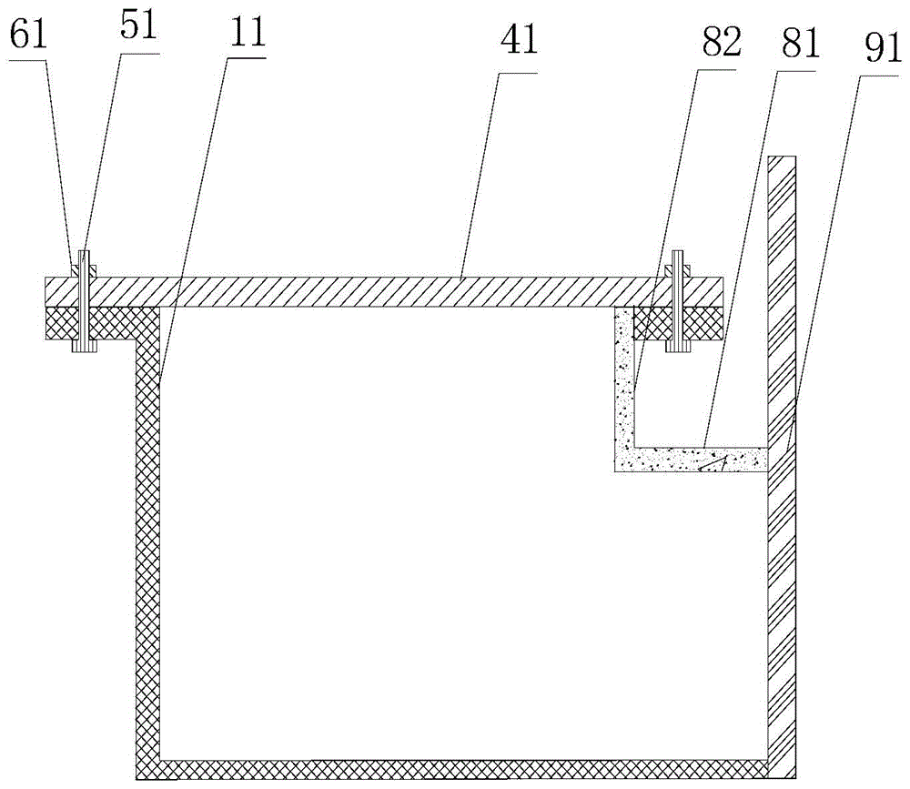
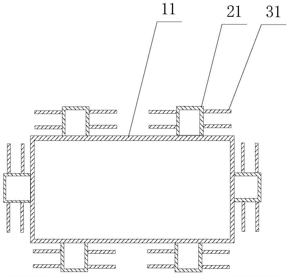
[0032] figure 2 The basic structural diagram of the transformer with automatic drainage function according to the embodiment of the present invention is schematically given, as figure 2 As shown, the transformer includes:
[0033] Front panel 91, coils, binding posts, etc., these components are all prior art in this field, and will not be repeated here;
[0034] The connecting part, the vertical section of the connecting part is "L" shape, has a vertical part 82 and a bottom 81, the bottom surface is inclined, the bottom and the vertical part are welded on the housing, and the right end is welded on the the rear side of the front panel;
[0035] Housing 11, the upper end of the housing has an outwardly bent horizontal portion, and the cover 41 is obliquely installed on the horizontal portion through bolts 51 and nuts 61; the cover 41 is arranged obliquely;
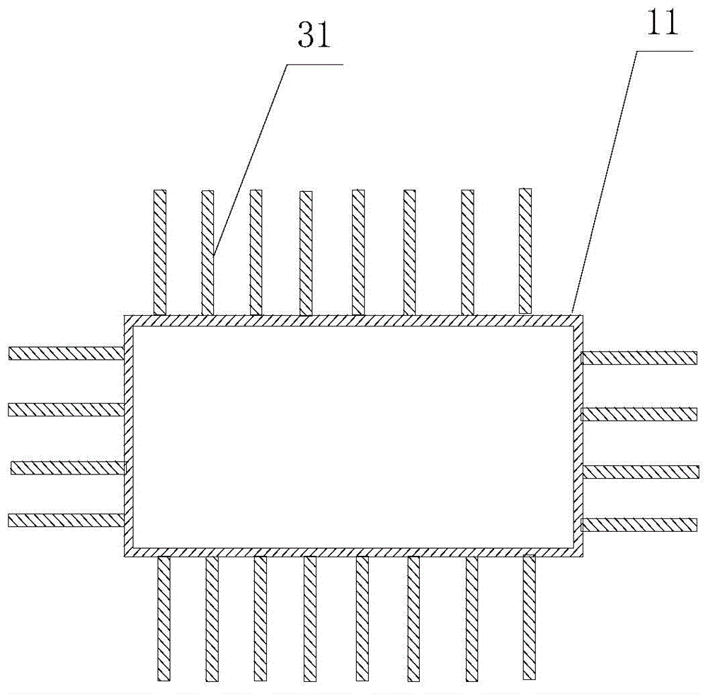
[0036] image 3 Schematically provides the basic structural diagram of the radiator of the embodiment of the prese...
PUM
 Abstract
Description
Claims
Application Information