Vertical substrate conveyer

A transfer device, a vertical technology, applied in the field of vertical substrate transfer devices, can solve the problems of carrier pollution, increase carrier maintenance and construction costs, destroy the preset accuracy of the carrier, etc., to reduce the walking distance and avoid pollution and cleaning and maintenance costs, and the effect of increasing substrate capacity

Inactive Publication Date: 2015-04-29
ARCHERS
View PDF5 Cites 4 Cited by
  • Summary
  • Abstract
  • Description
  • Claims
  • Application Information

AI Technical Summary

Problems solved by technology

However, the traditional carrier needs to be kept in the process chamber. With the process of plasma preparation, the carrier is easily polluted by factors such as accumulated dust, heat bending deformation, etc., which destroys the preset accuracy of the carrier, thus greatly increasing the Vehicle maintenance and construction costs

Method used


Image

  • Vertical substrate conveyer
  • Vertical substrate conveyer
  • Vertical substrate conveyer

Examples


Embodiment Construction

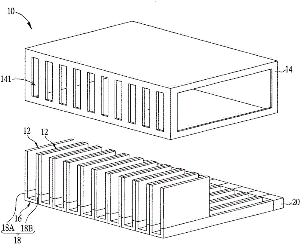
[0022] see figure 1 , figure 1 It is a schematic diagram of a vertical substrate transfer device 10 according to an embodiment of the present invention. The vertical substrate transfer device 10 operates in a vacuum environment, such as a high-temperature vacuum process environment preferably applied in a plasma system, and is used to move a substrate 12 from a transfer chamber to a process chamber. Wherein the substrate 12 is a large-size substrate of more than five generations. The vertical substrate transfer device 10 includes a cavity 14 , a plurality of cassettes 16 and a plurality of storage tanks 18 . The present invention has the function of accommodating multiple substrates 12 at the same time. For example, the vertical substrate transfer device 10 may include ten cassettes 16 and twenty storage slots 18, and each cassette 16 is movably arranged on the Inside the cavity 14 , each cassette 16 is provided with two storage slots 18A and 18B, and each storage slot 18 c...


PUM


Abstract

A vertical substrate conveyer comprises a conveying mechanism, a propelling mechanism and a power source. The conveying mechanism is use for conveying a substrate. The conveying mechanism comprises a roller and a limiting piece. The propelling mechanism is arranged beside the conveying mechanism. The propelling mechanism comprises a base, at least one clamping unit, a rail and a push rod. The clamping unit is arranged on the base and used for grabbing the substrate. The rail is arranged on the base. The push rod is arranged in the rail in a slidable manner and used for pushing the substrate to move along the roller. The power source is electrically connected with the conveying mechanism and the propelling mechanism. The power source drives the clamping unit to grab and loosen the substrate and further drives the roller to rotate and the push rod to slide to move the substrate.

Description

technical field [0001] The invention provides a substrate conveying device, especially a vertical substrate conveying device which can effectively prevent dust pollution and has a two-stage moving stroke. Background technique [0002] In the traditional plasma system process, the substrate is generally transported by using a robot arm to grab and transport, and using a carrier to carry the substrate and then transport it. The traditional robotic arm is equipped with a set of liftable support columns. The disadvantage is that each robotic arm can only grab one substrate, so it takes up more space for the system's mechanism configuration, which in turn leads to an increase in system cost. The traditional carrier is to use rollers or push rods to drive the carrier after loading the substrate, so as to achieve the function of moving the substrate. However, the traditional carrier needs to be kept in the process chamber. With the process of plasma preparation, the carrier is eas...

Claims


Application Information

Patent Timeline
Patent Type & Authority Applications(China)
IPC IPC(8): H01L21/677
CPCH01L21/677H01L21/67712H01L21/68H01L21/68721
Inventor 刘品均曹承育黄正忠
Owner ARCHERS
Why Eureka
Try Eureka