Transparent cover layers for solar cells and modules

A technology of solar cells and covering layers, applied in circuits, photovoltaic power generation, electrical components, etc., can solve problems such as reducing the efficiency of solar energy installations

Active Publication Date: 2017-06-13
TAIWAN SEMICON MFG CO LTD
View PDF9 Cites 0 Cited by
  • Summary
  • Abstract
  • Description
  • Claims
  • Application Information

AI Technical Summary

Problems solved by technology

Therefore, the loss of light through the protective covering reduces the efficiency of solar installations

Method used


Image

  • Transparent cover layers for solar cells and modules
  • Transparent cover layers for solar cells and modules
  • Transparent cover layers for solar cells and modules

Examples


example

[0073] A conventional protective covering (C00) consisting of glass is provided. For comparison, a transparent cover layer (C01) was produced according to the method described in the present invention. A thin film with Cu nanoparticles was deposited onto the front glass between the anti-reflective coating and the front glass. The thin film has a thickness of about 5 to 10 nm. The coating was annealed at 350 °C for 30 min. The transmittance of light through each cover layer C00 and C01 was measured.

[0074] Figure 15 Data are shown for the transmittance of light through C00 and C01 at various wavelengths. For wavelengths between about 450nm to 950nm, the C01 transparent cover layer has a higher transmission than the C00 glass. The highest observed transmission of the C01 transparent cover layer was about 95%, while the highest observed transmission of the C00 glass was about 92%.

[0075] In summary, the disclosed methods and transparent cover layers allow for increased...


PUM


Abstract

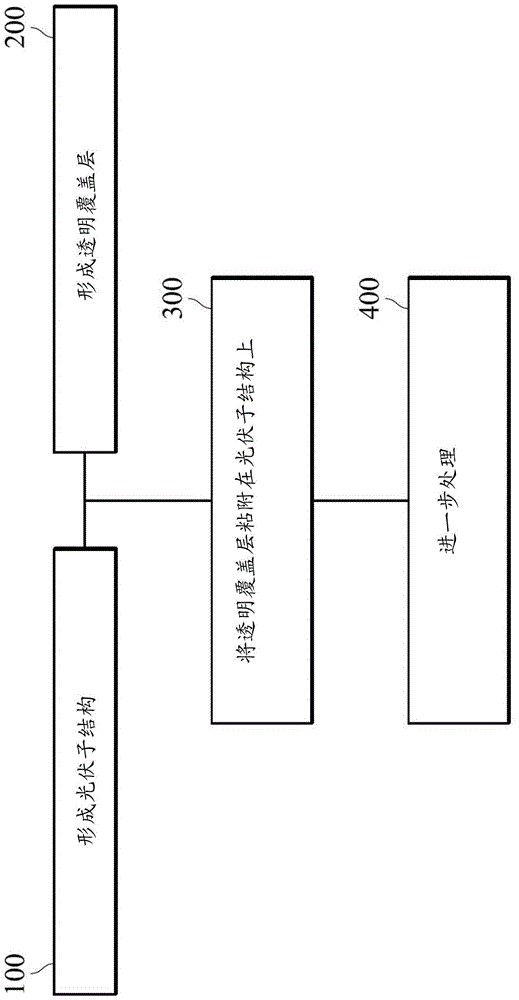
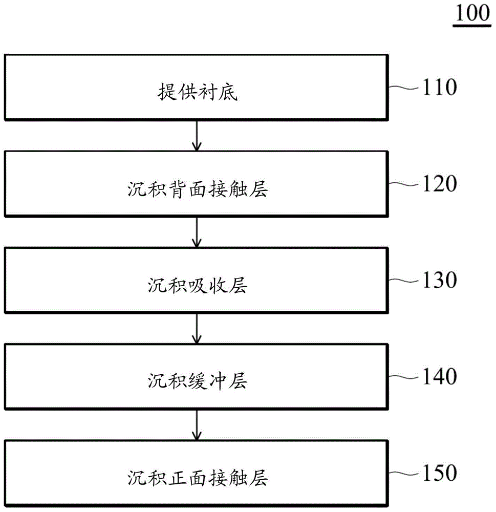
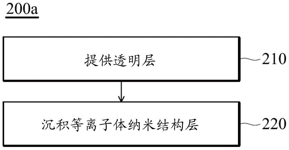
The present invention describes a solar cell device and a method of manufacturing the same. A method of fabricating a solar cell comprising forming a photovoltaic substructure comprising a substrate, a back contact layer, an absorber layer and a buffer layer, forming a transparent cover layer separate from the photovoltaic substructure comprising a transparent layer and a layer of plasmonic nanostructures in contact with the transparent layer , and attaching a transparent cover layer on top of the photovoltaic substructure. The plasmonic nanostructure layer may include metal nanoparticles. The invention also provides transparent cover layers for solar cells and modules.

Description

technical field [0001] The present invention relates to photovoltaic solar cells and solar modules. More specifically, the present invention relates to a transparent cover layer for a solar module and a method of manufacturing the same. Background technique [0002] A solar cell is a power generating device that directly generates electricity from sunlight. A plurality of solar cells may be connected through respective interconnect structures to form a solar cell module. Multiple modules can be connected to form an array. [0003] Some solar cell devices include a protective cover over the solar cells. Sunlight passes through the protective covering to the underlying solar cells to be converted into electrical current through the photovoltaic effect. The optical transmittance through the protective cover affects the efficiency of the solar cell device. For example, the amount of electricity generated by a solar cell depends on the amount of light passing through the pro...

Claims


Application Information

Patent Timeline
Patent Type & Authority Patents(China)
IPC IPC(8): H01L31/0216H01L31/0232H01L31/048H01L31/055
CPCH01L31/048G02B5/008H01L31/02168H01L31/0232H01L31/055H01L31/18Y02E10/52
Inventor 吴志力严文材徐伟伦
Owner TAIWAN SEMICON MFG CO LTD
Why Eureka
Try Eureka