Laminated core and method for manufacturing the same

一种叠层铁芯、制造方法的技术,应用在制造定子/转子本体、电气元件、磁路静止零部件等方向,能够解决电机性能降低等问题,达到面积增加、接合强度增大、防止剥离的效果

Active Publication Date: 2015-04-29
MITSUI HIGH TEC INC
View PDF7 Cites 10 Cited by
  • Summary
  • Abstract
  • Description
  • Claims
  • Application Information

AI Technical Summary

Problems solved by technology

However, when the core pieces are joined by fastening and welding, the core pieces are conducted in the lamination direction, and there is a problem that eddy current loss is generated and the performance of the motor deteriorates.

Method used


Image

  • Laminated core and method for manufacturing the same
  • Laminated core and method for manufacturing the same
  • Laminated core and method for manufacturing the same

Examples


Embodiment Construction

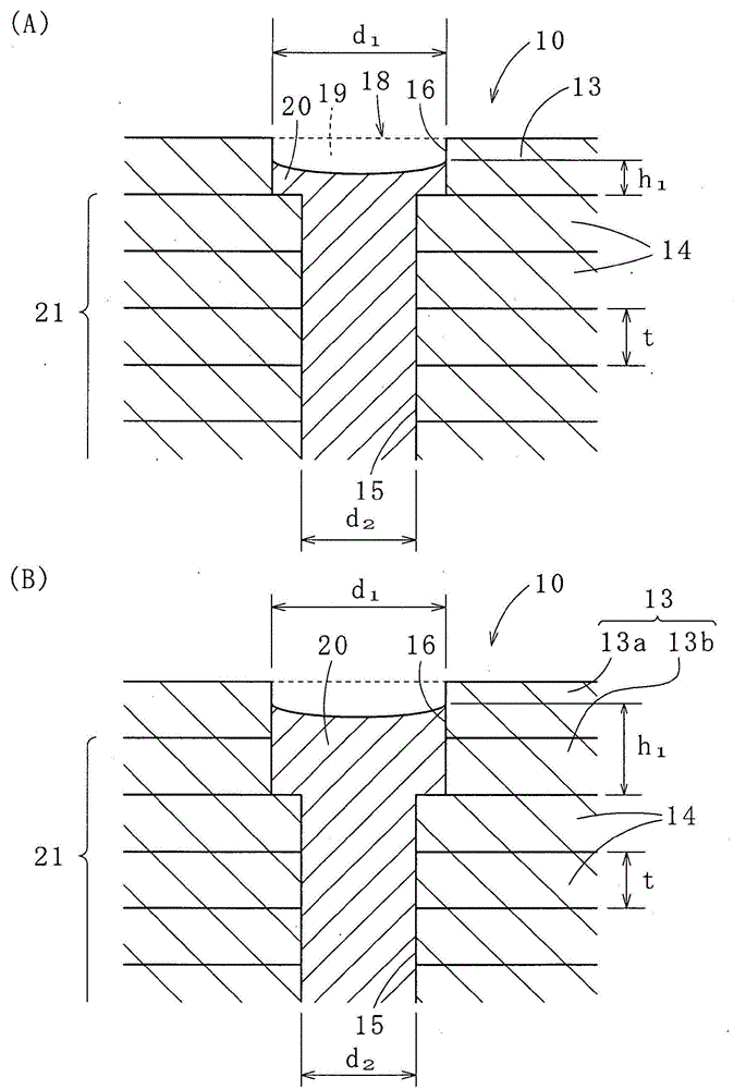
[0048] Next, specific embodiments of the present invention will be described with reference to the drawings. In the following embodiments, the core pieces on one side (specifically, the upper end) of the laminated iron core will be described, but the core pieces on the other side (specifically, the lower end) may have the same structure.

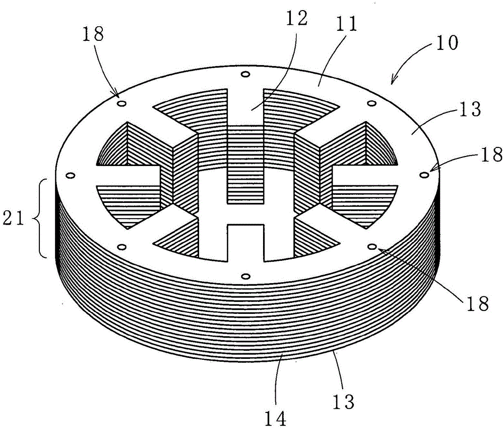
[0049] In addition, in the following embodiments, the stator laminated core will be mainly described, but it is also applicable to the rotor laminated core.

[0050] In addition, in the present invention including the following embodiments, the core sheet at the end in the axial direction is referred to as a core sheet (A), and the other core sheets are referred to as a core sheet (U), and are only referred to as "core sheets". It refers to the case of including the chip (A) and the chip (B) or generally referred to as the chip. In addition, in the present invention, the laminated core includes a case where the core pieces are only laminate...


PUM


Abstract

A laminated core 10 including a plurality of laminated iron core pieces, each of the iron core pieces being connected in a laminating direction by filling resin in a plurality of resin holes penetrating the laminated core 10 in the laminating direction, and a method for manufacturing the laminated core 10, by making a junction area of an iron core piece (A) 13 and resin larger than a junction area of an iron core piece (U) 14 and resin, the iron core piece (A) 13 being provided on an end in an axial direction, the iron core pieces (U) 14 being arranged at positions other than the end in the axial direction, or by providing locking portions at tip portions of resin, acquired joint strength of the iron core piece (A) 13.

Description

technical field [0001] The present invention relates to a laminated core (including a rotor laminated core and a stator laminated core) in which core pieces are connected by resin filled in resin holes (through holes) and a method of manufacturing the same. Background technique [0002] As a method of manufacturing a laminated iron core, for example, a method of forming a laminated iron core by laminating, fastening, welding, etc. joining the core sheets to form a laminated iron core is widely used. However, when the core pieces are joined by fastening and welding, the core pieces are conducted in the lamination direction, and there is a problem that eddy current loss is generated and the performance of the motor deteriorates. [0003] In order to solve this problem, there are the following methods, namely, Figure 13 As shown in (A) and (B), the resin 92 is injected into the resin hole 91 connecting the plurality of through-holes provided on the core sheet 90 in the laminat...

Claims


Application Information

Patent Timeline
Patent Type & Authority Applications(China)
IPC IPC(8): H02K1/06H02K15/02
CPCH02K1/06H02K15/02H02K2201/09H02K1/22H02K1/12
Inventor 福本崇小田仁手冢升吾绪方萌
Owner MITSUI HIGH TEC INC
Why Eureka
Try Eureka