
Permanent magnet synchronous motor

A permanent magnet synchronous motor and permanent magnet technology, which is applied to synchronous motors with stationary armatures and rotating magnets, magnetic circuits, electric components, etc., can solve problems such as increased production costs and complex production processes, and achieve cogging rotation Reduced torque, uniform magnetic force distribution, and the effect of meeting the requirements of low cogging torque

Inactive Publication Date: 2015-04-29
大工科技(上海)有限公司
View PDF3 Cites 0 Cited by
  • Summary
  • Abstract
  • Description
  • Claims
  • Application Information

AI Technical Summary

Problems solved by technology

However, the production process of the inclined pole or the chute is complicated, and the production cost increases

Method used

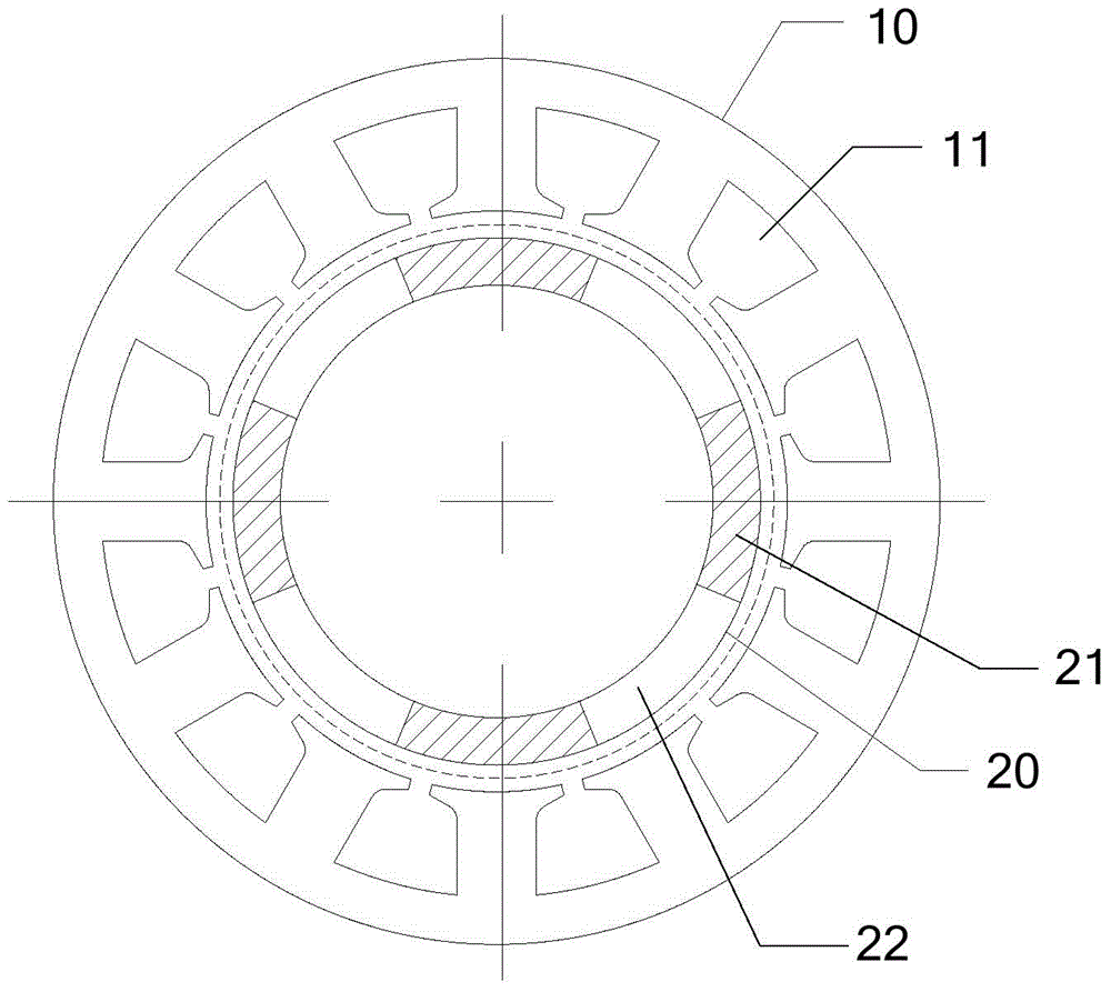
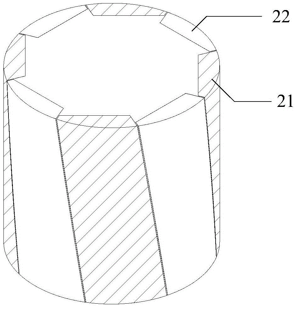

Image

  • Permanent magnet synchronous motor
  • Permanent magnet synchronous motor
  • Permanent magnet synchronous motor

Examples


Embodiment Construction

[0016] The following will clearly and completely describe the technical solutions in the embodiments of the present invention with reference to the accompanying drawings in the embodiments of the present invention. Obviously, the described embodiments are only some, not all, embodiments of the present invention. Based on the embodiments of the present invention, all other embodiments obtained by persons of ordinary skill in the art without creative efforts fall within the protection scope of the present invention.

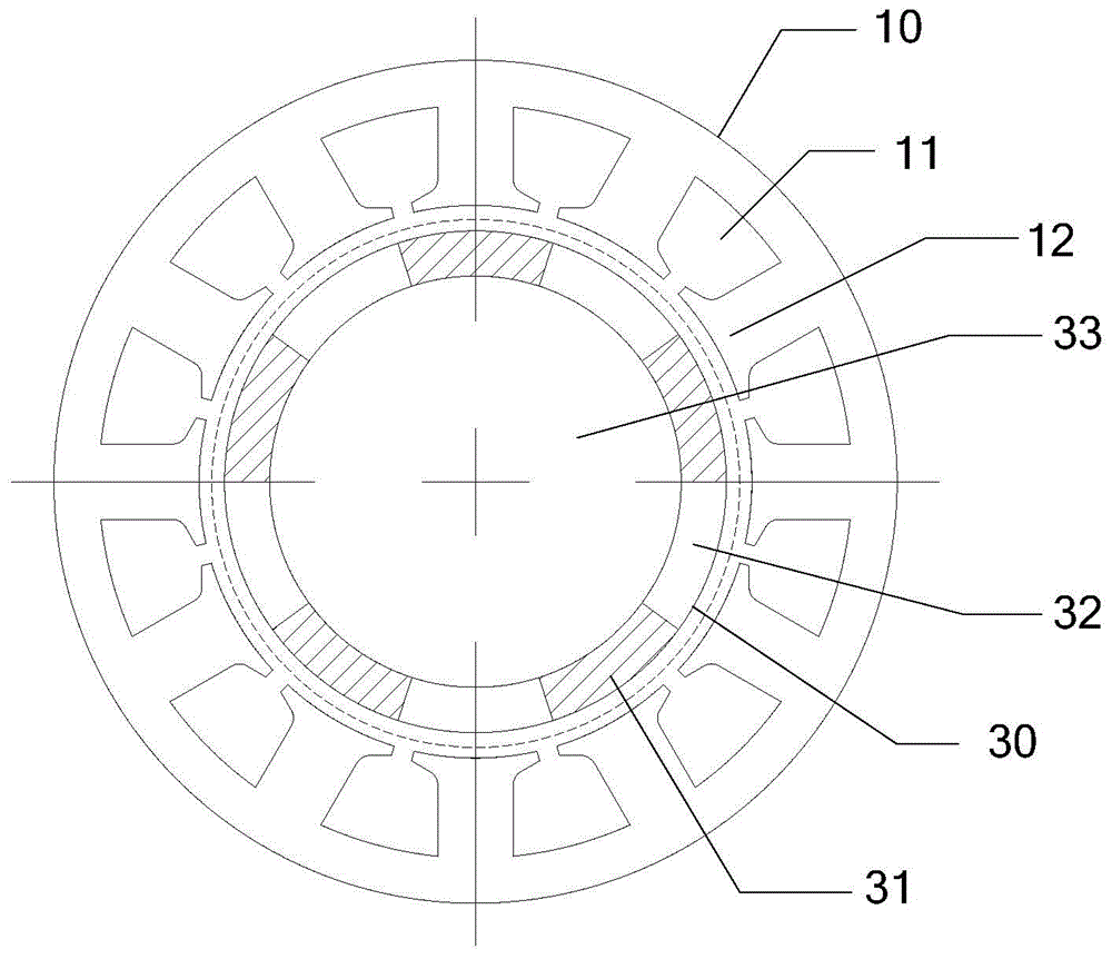
[0017] see image 3 , the embodiment of the present invention discloses a sectional view of a permanent magnet synchronous motor. The permanent magnet synchronous motor includes: a twelve-slot stator 10 ( image 3 The outer part of the dotted line circle) and the ten-pole rotor 30 ( image 3 The inner part of the dotted line circle), wherein the twelve-slot stator 10 is arranged outside the ten-pole rotor 30 .

[0018] Specifically, the twelve-slot stator 10 incl...


PUM


Abstract

The invention provides a permanent magnet synchronous motor. The permanent magnet synchronous motor adopts a scheme of twelve slots and ten poles, wherein twelve-slot stators are arranged on the outer sides of ten-pole rotors; from the distribution characteristics of the twelve-slot stators and the ten-pole rotors, in the ten-pole rotors, the total quantities of the stator slots corresponding to permanent magnets with the outer rings as south pole and the stator slots corresponding to the permanent magnets with the outer rings as north pole are both six, so that the ten-pole rotors realize the situation that at any moment, the magnetic forces of the permanent magnets with the outer rings as the south pole and the permanent magnets with the outer rings as the north pole are basically identical, the magnetic force of the ten-pole rotor is distributed uniformly in the rotating process, and the cogging torque can be greatly reduced. Therefore, the twelve-slot ten-pole permanent magnet synchronous motor provided by the invention can greatly reduce the cogging torque, and meets the low cogging torque requirement on the permanent magnet synchronous motor in the actual application process under the situation that the production technology and the production cost are basically invariable.

Description

technical field [0001] The present invention relates to the technical field of motors, more specifically, to a permanent magnet synchronous motor. Background technique [0002] When the armature winding is not energized, the tangential force generated in the circumferential direction between the magnetic field generated by the permanent magnet and the stator core makes the rotor of the permanent magnet synchronous motor have a tendency to align with the stator along a certain direction , try to locate the rotor in some specific position, the oscillation torque generated by this tendency is called the cogging torque of the permanent magnet synchronous motor. [0003] Since the smaller the cogging torque, the smaller the vibration when the motor rotates, the higher the efficiency of the permanent magnet synchronous motor, and the better the control accuracy, so the smaller the cogging torque of the permanent magnet synchronous motor, the better. Among them, a method to reduce...

Claims


Application Information

Patent Timeline
Patent Type & Authority Applications(China)
IPC IPC(8): H02K21/16H02K1/27
CPCH02K21/16H02K1/278H02K2213/03
Inventor 陈杨钟梁兆明
Owner 大工科技(上海)有限公司
Learn More