Double-output DC-DC oscillator circuit

A DC-DC, oscillator technology, applied in the field of DC-DC oscillator circuit, can solve problems such as large RMS current and mutual interference

Active Publication Date: 2015-04-29
SANMENXIA SUDA TRANSPORTATION ENERGY SAVING TECH
View PDF7 Cites 1 Cited by
  • Summary
  • Abstract
  • Description
  • Claims
  • Application Information

AI Technical Summary

Problems solved by technology

[0004] The object of the present invention is to overcome above-mentioned deficiency, provide a kind of dual-output DC-DC oscillator circuit, sol...

Method used


Image

  • Double-output DC-DC oscillator circuit
  • Double-output DC-DC oscillator circuit
  • Double-output DC-DC oscillator circuit

Examples


Embodiment 1

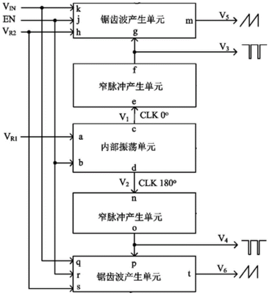
[0056] see figure 1 , the present invention includes an internal oscillating unit capable of generating a constant clock signal, a first narrow pulse generating unit and a second narrow pulse generating unit capable of converting the internal clock signal into a narrow pulse signal with a fixed pulse width, and generating two phase differences 180 The first sawtooth wave generation unit and the second sawtooth wave generation unit of the sawtooth wave signal;

[0057] The internal oscillating unit is respectively connected to the first narrow pulse generating unit and the second narrow pulse generating unit, and the internal oscillating unit is connected to the reference voltage V R1 and the enable signal EN, the phase difference between the constant clock signal output by the internal oscillation unit to the first narrow pulse generating unit and the constant clock signal output to the second narrow pulse generating unit is 180 degrees, the first narrow pulse generating unit ...

Embodiment 2

[0094] The internal oscillating unit and the narrow pulse generating unit of this embodiment are the same as those in Embodiment 1, and the circuit of the tooth wave generating unit is changed.

[0095] see Figure 5 , the circuit structure of the first sawtooth wave generation unit and the second sawtooth wave generation unit are the same, and both include an error amplifier 301, a second D flip-flop 302, a ninth inverter 303, an NMOS transistor M 301 , NMOS tube M 303 , NMOS tube M 305 , NMOS tube M 307 , NMOS tube M 311 , PMOS tube M 302 , PMOS tube M 304 , PMOS tube M 306 , PMOS tube M 308 , the third capacitor C 3 , the fourth capacitor C 4 and current source I R3 ;

[0096] The non-inverting input terminal of the error amplifier 301 is connected to the reference voltage V R2 , the inverting input terminal is connected to its output terminal, and at the same time it is connected to the NMOS transistor M 301 , NMOS tube M 305 and PMOS tube M 302 , PMOS tube ...

Embodiment 3

[0104] The internal oscillating unit and the sawtooth wave generating unit of this embodiment are the same as those in Embodiment 1, and the circuit of the narrow pulse generating unit is changed.

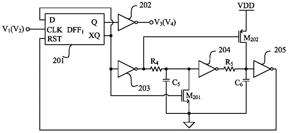
[0105] see Figure 6 , the circuit structure of the first narrow pulse generating unit and the second narrow pulse generating unit are the same, both including the first D flip-flop 201, the fifth inverter 202, the sixth inverter 203, the NAND gate 204, the eighth inverter Phase device 205, tenth inverter 206, seventh capacitor C 7 ;

[0106] The clock input terminal CLK of the first D flip-flop 201 is connected to V 1 or V 2 , its input terminal D is connected to the input terminal of the tenth inverter 206, and is connected to one of its output terminals XQ at the same time, the output terminal XQ of the first D flip-flop 201 is connected to the input terminal of the sixth inverter 203, and the reset terminal RST is connected to The output end of the eighth inverter 205, the ...


PUM


Abstract

The invention discloses a double-output DC-DC oscillator circuit. When reference voltage VR1 and an enable signal EN are added, an internal oscillation circuit generates square signals V1 and V2 which are fixed and identical in frequency and opposite in phase, two channels of narrow-pulse signals V3 and V4 with the phase difference of 180 degrees are generated by the aid of two pulse generating circuits, the two channels of narrow-pulse signals can be directly used as output signals of the circuit to trigger switching on of a switching tube, two channels of sawtooth signals V5 and V6 with the phase difference of 180 degrees are generated by the aid of a sawtooth wave generating circuit under the action of input voltage VIN, reference voltage VR2 and the enable signal EN respectively to be used as the other kind of output signals of the circuit, the RMS current of double channels of DC-DC input is effectively decreased, and the interference between two channels of output is eliminated. A ramp voltage signal is provided by a sawtooth wave generating unit of the oscillator circuit, and the ramp voltage signal capable of realizing ramp low-level control and input voltage feed-forward control enhances the stability of a voltage-mode loop.

Description

technical field [0001] The invention belongs to the field of electronic circuits, and in particular relates to a dual-output DC-DC oscillator circuit. Background technique [0002] Due to the advantages of high conversion efficiency, DC-DC converters have been widely used in electronic systems. With the development of electronic systems, monolithic integrated multi-output DC-DC converters have the advantages of high integration and simple system design, and have become a hot issue in the research of DC-DC converters. However, multi-output DC-DC converters still face key problems such as large input RMS current and mutual interference between channels. DC-DC converters tend to develop at high frequencies, and the increase in switching frequency can reduce DC-DC converters proportionally. Output the volume of the LC filter device, and even realize the integration of the inductor. [0003] The loop of the voltage-mode DC-DC converter does not need to periodically sample the i...

Claims


Application Information

Patent Timeline
IPC IPC(8): H02M1/44
CPCH03K4/48H03K7/08
Inventor 李演明吴凯凯柴红张豪仝倩杨晓冰文常保邱彦章
Owner SANMENXIA SUDA TRANSPORTATION ENERGY SAVING TECH
Why Eureka
Try Eureka