Method for controlling the motor of a pump involving the determination and synchronization of the point of maximum torque with a table of values used to efficiently drive the motor

a technology of maximum torque and motor, which is applied in the direction of pump control, dc motor speed/torque control, motor parameter, etc., can solve the problem of increasing the rms current problem, excessive heating of the motor, and higher than necessary load on the power source, so as to reduce the rms current in the motor

Inactive Publication Date: 2005-12-27
MOOG INC
View PDF14 Cites 38 Cited by
  • Summary
  • Abstract
  • Description
  • Claims
  • Application Information

AI Technical Summary

Benefits of technology

[0005]The present invention relates to a method that can be utilized by a drive system containing a microcomputer to control the speed of the electric motor in such a way as to level the load on the motor, and thereby reduce RMS current in the motor.

Problems solved by technology

A technical problem in driving a pump load with an electric motor is that the highly cyclic torque load of the pump produces a high RMS current in the motor, resulting in excessive heating in the motor and higher than necessary loading on the power source.
If the electronic control for the motor is required to maintain a constant speed during this pump cycle, as is often specified, the RMS current problem becomes even greater.

Method used


Image

  • Method for controlling the motor of a pump involving the determination and synchronization of the point of maximum torque with a table of values used to efficiently drive the motor
  • Method for controlling the motor of a pump involving the determination and synchronization of the point of maximum torque with a table of values used to efficiently drive the motor
  • Method for controlling the motor of a pump involving the determination and synchronization of the point of maximum torque with a table of values used to efficiently drive the motor

Examples


Embodiment Construction

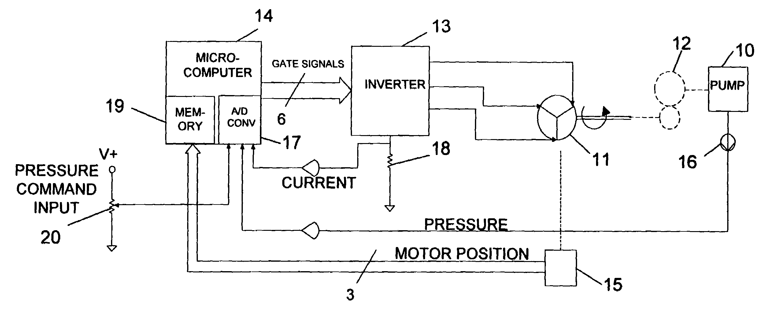
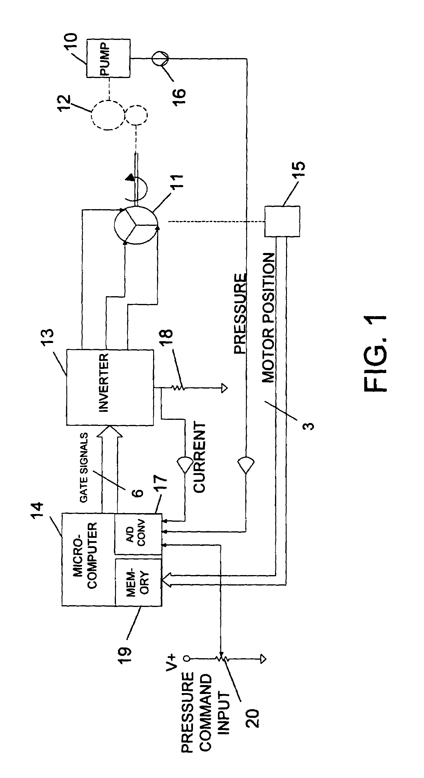
[0016]The present invention is made in the context of a motor control system seen in FIG. 1. A pump 10 is coupled to the output shaft of an electric motor 11 through a gear mechanism12. The motor 11 is a three-phase brushless DC motor which is commutated through an inverter 13 according to switching signals received from a microcomputer 14. The motor 11 is provided with a position sensor 15, which in this embodiment is provided by Hall devices, but could also be provided by an encoder or a resolver. The position sensor 15 provides MOTOR POSITION feedback signals to the microcomputer 14. In addition, the pump 10 has a pressure sensor 16 which provides a PRESSURE feedback signal to an A-to-D conversion section 17 of the microcomputer 14. A current sensing device 18 is installed in the inverter 13 and provides a CURRENT feedback signal to the A-to-D conversion section 17 of the microcomputer 14. Also shown in FIG. 1 is an input device 20 for commanding a level of average pressure for t...


PUM


Abstract

A method for controlling a motor (11) driving a pump (10) using a microcomputer (14) includes repeatedly sampling a parameter representative of motor torque over one cycle of operation of the pump (10), determining at least one point of maximum motor torque during said one cycle of operation of the pump (FIG. 4); applying speed commands to the motor (11) from a table of stored speed values in memory (19), said values being selected to provide relatively greater speed commands at points of lower motor torque and relatively lesser speed commands at points of higher pump pressure corresponding to higher motor torque, while maintaining at least a base speed command to prevent stalling; and synchronizing the first value in the table of stored values to the point of maximum motor torque.

Description

TECHNICAL FIELD[0001]The field of the invention is methods and electronic motor controls for controlling a motor that drives a cyclical pump load.DESCRIPTION OF THE BACKGROUND ART[0002]Piedl et al., PCT Pub. No. WO 00 / 25416, published May 4, 2000, discloses a system for controlling a pump load, in which the pump is coupled to an electric motor through a crankshaft, such that pump operation is sensed indirectly to eliminate the need for a pressure sensor or a position sensor.[0003]Bert et al., U.S. Pat. No. 6,074,170, shows that it is known in the art to sense pump pressure and to adjust the speed of the motor in response to pump pressure using a microcomputer. This system regulates pump pressure through a pressure loop operating at about 3 Hz.[0004]A technical problem in driving a pump load with an electric motor is that the highly cyclic torque load of the pump produces a high RMS current in the motor, resulting in excessive heating in the motor and higher than necessary loading on...

Claims


Application Information

Patent Timeline
Patent Type & Authority Patents(United States)
IPC IPC(8): F04B49/06F04B49/20
CPCF04B49/065F04B2203/0207
Inventor KIDD, HOWARD KEITH
Owner MOOG INC
Why Eureka
Try Eureka