
Novel Z-source grid-connected inverter

A converter and a new type of technology, applied in the field of converters and new Z-source grid-connected converters, can solve the problems of inability to achieve abnormal working conditions, high capacitor voltage stress, large inrush current, etc., and achieve output waveform distortion. Small, low capacitor voltage stress, low starting impulse current effect

Inactive Publication Date: 2015-04-29
BEIJING INSTITUTE OF TECHNOLOGYGY
View PDF6 Cites 17 Cited by
  • Summary
  • Abstract
  • Description
  • Claims
  • Application Information

AI Technical Summary

Problems solved by technology

[0006] The purpose of the present invention is to provide a bidirectional converter based on the Z source network for the problems of large start-up surge current, high capacitor voltage stress, abnormal working state and inability to realize bidirectional flow of energy in the traditional Z source inverter.

Method used


Image

  • Novel Z-source grid-connected inverter
  • Novel Z-source grid-connected inverter
  • Novel Z-source grid-connected inverter

Examples


Embodiment

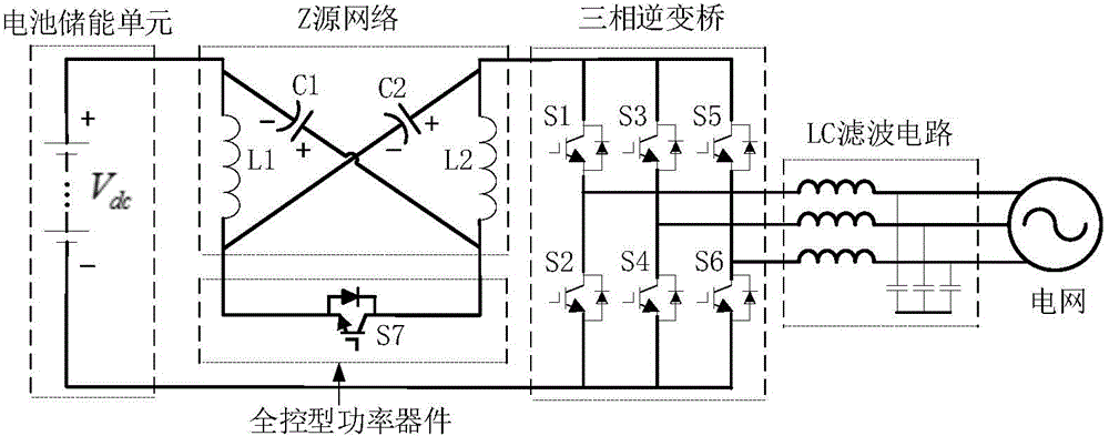
[0027] figure 1 It is a topological structure diagram of a new Z-source grid-connected converter of the present invention. The converter mainly includes a battery energy storage unit, a Z-source network, a fully-controlled power device, a three-phase inverter bridge and an LC filter circuit. The battery energy storage unit, the Z source network, the three-phase inverter bridge, and the LC filter circuit are connected in sequence, the Z source network is connected in series between the battery energy storage unit and the three-phase inverter bridge, and the fully-controlled power device is connected to the Z source network on the other hand. between the two ports.

[0028] Specifically, the battery energy storage unit is composed of a chargeable and dischargeable storage battery, which may be a lead-acid battery, a lithium-ion battery, or the like.

[0029] Specifically, the Z source network is composed of two equivalent inductors L1, L2 and two equivalent capacitors C1, C2, t...


PUM


Abstract

The invention relates to a novel Z-source grid-connected inverter, and belongs to the technical field of power electronic converters. The novel Z-source grid-connected inverter comprises a battery energy storage unit, a Z-source network, a full-controlled type power device, a three-phase inverter bridge and an LC filtering circuit. The positive electrode of the battery energy storage unit is connected with the input end of the Z-source network, the output end of the Z-source network is connected with the positive end of the three-phase inverter bridge, the negative end of the three-phase inverter bridge is connected with the negative electrode of the battery energy storage unit, the Z-source network is connected between the battery energy storage unit and the three-phase inverter bridge in series, the other two ports of the Z-source network are connected with the full-controlled type power device, and the output of the three-phase inverter bridge is connected to a power grid through the LC filtering circuit. Compared with a traditional voltage source inverter of a single-stage structure, boost-buck conversion can be achieved, an upper switching tube and a lower switching tube of the same bridge arm of the inverter bridge are allowed to be directly connected, work reliability is higher, no dead zone needs to be added, and output waveform distortion is small. Compared with a traditional Z-source inverter, start impact currents are small, capacitor voltage stress is low, two-way energy flow is allowed, and the circuit structure is simple.

Description

technical field [0001] The invention relates to a converter, in particular to a novel Z-source grid-connected converter, which belongs to the technical field of power electronic converters. technical background [0002] Power electronic converters are widely used in many occasions such as locomotive traction, new energy power generation, motor drive, etc., providing conditions for human production and efficient use of energy. The power electronic converter commonly used in these occasions is an inverter, which converts direct current into alternating current. Traditional inverter circuit topology can be divided into voltage source inverter circuit and current source inverter circuit, and most of them are voltage source inverter circuits in practical applications. [0003] The voltage source inverter circuit is composed of a DC voltage source and a three-phase inverter bridge. Each bridge arm of the three-phase inverter bridge is composed of two full-control switch tubes con...

Claims


Application Information

Patent Timeline
Patent Type & Authority Applications(China)
IPC IPC(8): H02M7/5387H02J3/38
CPCH02M7/797H02J3/38
Inventor 高志刚樊辉
Owner BEIJING INSTITUTE OF TECHNOLOGYGY
Learn More