
Control device and method for reduction of inrush starting current of microwave tube in microwave oven

A technology for starting inrush current and control device, applied in output power conversion devices, microwave heating, electrical components and other directions, can solve the problems of inconsistent operation time of microwave tube control relays, large circuit structure, large inrush current, etc., to overcome the market. Electric voltage fluctuation, small circuit structure, small impact current effect

Active Publication Date: 2013-03-27
MIDEA GRP CO LTD
View PDF5 Cites 0 Cited by
  • Summary
  • Abstract
  • Description
  • Claims
  • Application Information

AI Technical Summary

Problems solved by technology

Among the above three methods, method one is not feasible at all, and it is easy to generate a large inrush current at the moment of microwave tube start-up. Although methods two and three can adjust one set in the experiment, in mass production, each circuit board is There are a large number of electronic components on it, and each electronic component has certain differences. The mains power will also fluctuate frequently, and the ambient temperature will also be different. These may cause the action time of the microwave tube control relay to be inconsistent, resulting in a large Inrush current, the third method is more complex circuit, large circuit structure, high cost
A large inrush current will impact the entire power grid, cause interference to other electrical appliances used in the power grid, and also cause damage to the switch contacts in the circuit, especially the contacts of the microwave tube control relay and the interlocking device of the furnace door switch. The contacts of the micro switch in the middle of the circuit may be melted and adhered seriously, and once the two contacts are adhered, microwaves will leak, causing extremely serious consequences

Method used

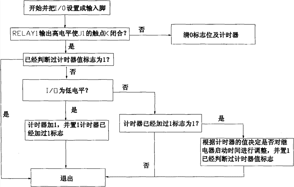
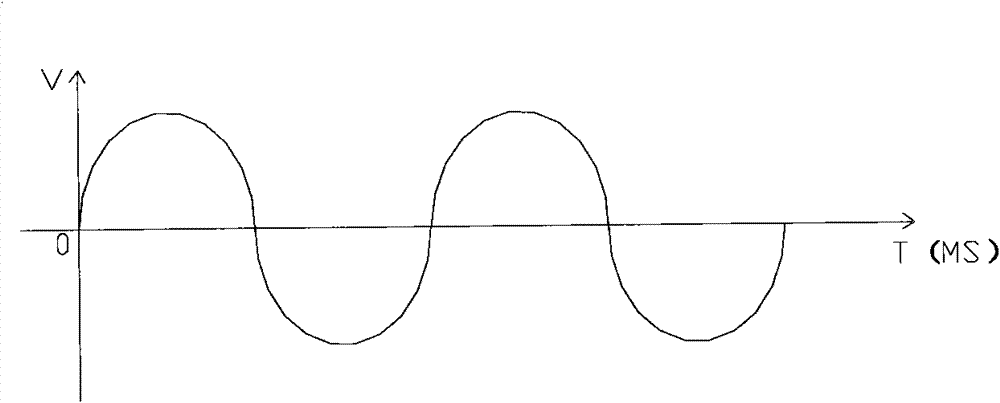

Image

  • Control device and method for reduction of inrush starting current of microwave tube in microwave oven
  • Control device and method for reduction of inrush starting current of microwave tube in microwave oven
  • Control device and method for reduction of inrush starting current of microwave tube in microwave oven

Examples


Embodiment Construction

[0022] The present invention will be further described below in conjunction with the accompanying drawings and embodiments.

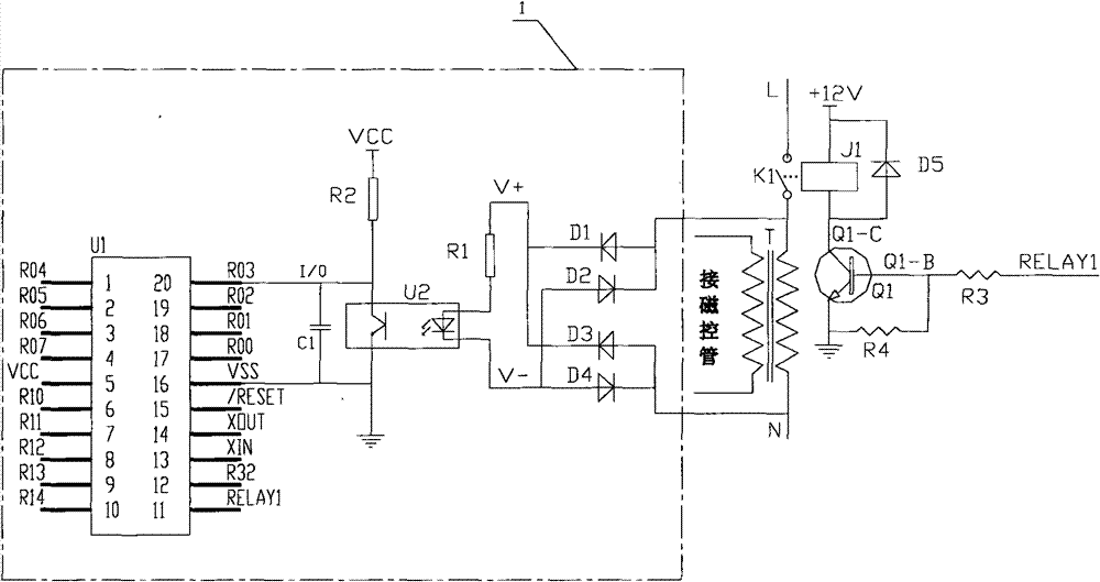
[0023] like figure 1 As shown, the microwave tube start-up surge current reduction control device for microwave ovens of the present invention includes an electric control board and a control chip U1, a microwave tube switch control device consisting of a relay J1, a diode D5, a triode Q1, a third resistor R3, and a fourth resistor R4. circuit, the electric control board is provided with a relay contact opening and closing detection circuit 1, and the relay contact opening and closing detection circuit 1 includes a bridge rectifier circuit D1, D2, D3, D4; an optocoupler circuit U2, R1, R2, C1, the input end of the bridge rectifier circuit is connected in parallel with the input end of the high-frequency transformer T, the positive pole of the output end of the bridge rectifier circuit is connected to the first resistor R1, and the other end of the first...


PUM


Abstract

The invention discloses a control device for reduction of inrush starting current of a microwave tube in a microwave oven, comprising an electrical control board, a control chip and a microwave tube switch control circuit. Mains supply is connected to a high-frequency transformer through the microwave tube switch control circuit, the electrical control board is provided with a relay contact on / off detection circuit, wherein the relay contact on / off detection circuit comprises a bridge rectifier circuit and an optocoupler circuit, the input end of the bridge rectifier circuit and the input end of the high-frequency transformer are connected in parallel, the anode of the bridge rectifier circuit is connected with a first resistor, the other end of the first resistor is connected with the anode of a light-emitting diode on the optocoupler circuit, the cathode of the light-emitting diode on the optocoupler circuit is connected with the cathode at the output end of the bridge rectifier circuit, the emitter at the output end of the optocoupler circuit is connected with the cathode of a control chip power supply, the collector at the output end of the optocoupler circuit is connected with the anode of the control chip power supply via a second resistor and connected to an I / O (Input / Output) detection port of the control chip, a capacitor is connected to the cathode of the control chip power supply through the port, and an RELAY 1 port of the control chip is used for controlling the on or off the microwave tube switch control circuit.

Description

technical field [0001] The invention relates to a control device and a control method for reducing the starting impulse current of a microwave tube of a microwave oven. Background technique [0002] The formation principle of the inrush current of the transformer is mainly due to the saturation of the magnetic circuit due to the external instantaneous current. The residual magnetism in the magnetic circuit intensifies the saturation, and the maximum impact of the residual magnetic flux makes the two superimposed in the same direction. The input resistance of the high-frequency transformer of the microwave oven is quite small, generally only a few ohms. When the mains power is applied to the input terminal of the high-frequency transformer, because the transformer is an inductive element, the electric energy cannot be immediately sensed by the output terminal and generate current output. , but to lag the voltage by 90 degrees, that is, 1 / 4 cycle, that is, when the voltage cro...

Claims


Application Information

Patent Timeline
Patent Type & Authority Patents(China)
IPC IPC(8): H05B6/68H02M1/36H02M1/32
Inventor 王晓华
Owner MIDEA GRP CO LTD
Learn More