
Tool arrangement

A technology for arranging structures and tools, applied in milling cutters, reamers, forming cutters, etc., can solve the problems of insufficient connection and insufficient use of thread tensile strength.

Active Publication Date: 2015-04-29
FRANZ HAIMER MASCHINENBAU KG
View PDF14 Cites 8 Cited by
  • Summary
  • Abstract
  • Description
  • Claims
  • Application Information

AI Technical Summary

Problems solved by technology

[0003] When screwing the tool into the tool receptacle via a threaded connection, the following problems can arise: Due to the elastic deformation of the thread flanks during screwing and clamping, only a small amount of thread path / thread lead takes place in the vicinity of the arranged clamping surface Bearer function
As a result, the tensile strength of the thread may not be fully utilized and the connection may not achieve maximum stability

Method used


Image

  • Tool arrangement
  • Tool arrangement
  • Tool arrangement

Examples


Embodiment Construction

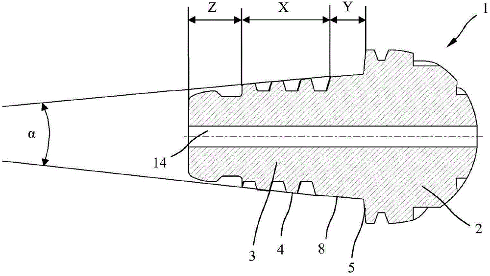
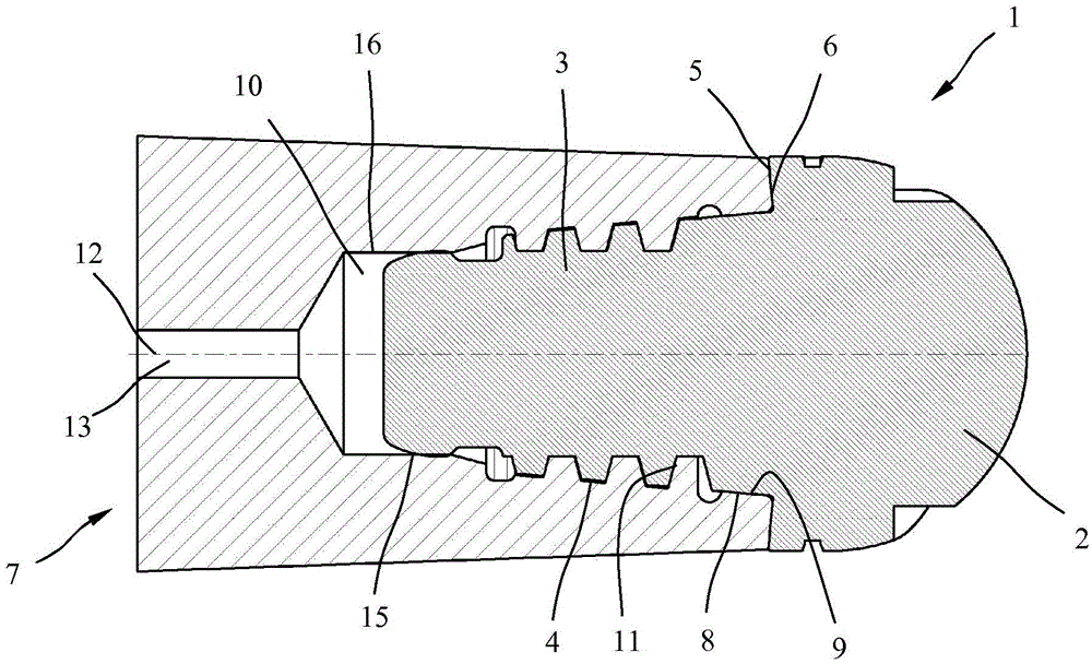
[0021] exist figure 1 A sectional view of the screw-in tool 1 is shown in the tool arrangement. The screw-in tool 1 has a tool head 2 , here designed as a ball-nose milling cutter, and a tool shank 3 tapering conically towards the rear. In the exemplary embodiment shown here, the tool shank 3 is divided into a thread region X with an external thread 4, a first outer bearing point Y arranged between the tool head 2 and the external thread 4, and a second external support point Y on the free end of the tool shank 3. Two internal support parts Z. However, the tool holder 3 can also be designed without an additional outer bearing point Y and / or without an inner bearing point Z.

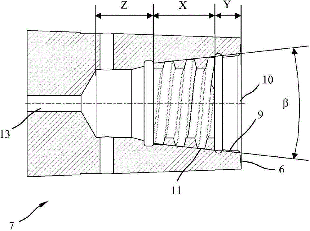
[0022] The external thread 4 in the thread point X tapers conically at a cone angle α. The first outer bearing point Y has a first conical contact surface 5 and a second conical contact surface 8 for abutting against a correspondingly conical bearing surface 6 on the front side of the tool receptacle 7...


PUM


Abstract

The invention relates to a tool arrangement with a screw-in tool (1) and a tool receiver (7), the screw-in tool (1) having a thread (4) for engagement in a counter thread (11) on the tool receiver (7). According to the invention, the counter thread (11) and the thread (4) have different thread contours and therefore, in the screwed condition, these adapt to one another by elastic deformation.

Description

technical field [0001] The invention relates to a tool arrangement according to the preamble of claim 1 . Background technique [0002] Such a tool arrangement is known from US Pat. No. 2,328,602, which consists of a screw-in tool and a tool receptacle configured as a device spindle. Provided on the screw-in tool is an external thread formed by a sawtooth thread, which engages into a corresponding internal thread on the tool receptacle. A conical bearing surface is also provided on the end side of the tool receptacle for concentric contact with a complementary counter-surface on the screw-in tool. [0003] When screwing the tool into the tool receptacle via a threaded connection, the following problems can arise: Due to the elastic deformation of the thread flanks during screwing and clamping, only a small amount of thread path / thread lead takes place in the vicinity of the arranged clamping surface Bearer function. As a result, the tensile strength of the thread may not ...

Claims


Application Information

Patent Timeline
Patent Type & Authority Applications(China)
IPC IPC(8): B23B31/11
CPCB23B31/005B23B31/1115B23C5/1009B23B2231/0204B23C2240/32B23C2240/245B23C2210/03B23C2210/02B23D2277/02B23D2277/066Y10T279/17931Y10T407/1948Y10T279/16B23B31/11B23C5/26B23B2265/08B23B2270/06
Inventor F·海莫
Owner FRANZ HAIMER MASCHINENBAU KG
Learn More