Method for releasing the pressure in a fuel system in a crash

A fuel system and fuel tank technology, which is applied in the layout, power plant, electric power plant, etc. combined with the fuel supply of internal combustion engines, can solve problems such as explosion, and achieve the effects of reducing cost, eliminating demand, and improving configurability.

Inactive Publication Date: 2015-04-29
PLASTIC OMNIUM ADVANCED INNOVATION & RES SA
View PDF3 Cites 5 Cited by
  • Summary
  • Abstract
  • Description
  • Claims
  • Application Information

AI Technical Summary

Problems solved by technology

this fire could cause an explosion

Method used


Image

  • Method for releasing the pressure in a fuel system in a crash

Examples


Embodiment Construction

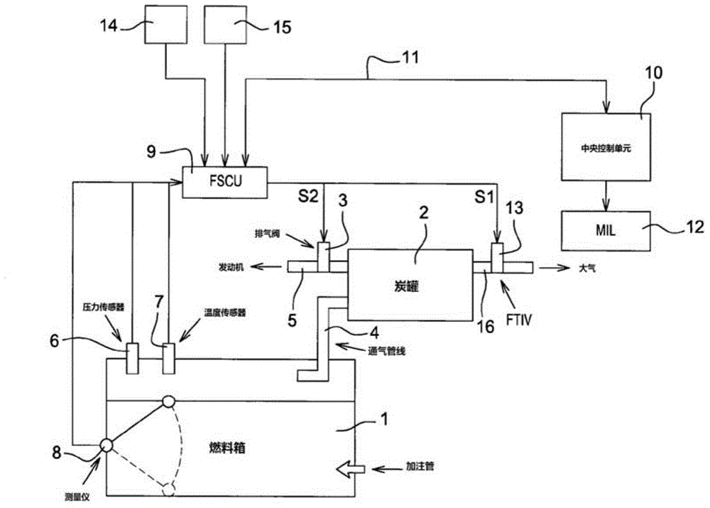
[0039] figure 1 A fuel system according to a particular embodiment of the invention is shown. The fuel system is installed on the vehicle. The fuel system includes a fuel tank 1 , and the fuel tank 1 communicates with a carbon canister 2 through a vent line 4 . The canister 2 has another breather line 5 connected to the intake manifold (not shown) of the internal combustion engine. An exhaust valve 3 is provided in the breather line 5 to enable selective communication between the canister 2 and an intake manifold (not shown). There is also an additional communication channel between the carbon canister 2 and the atmosphere. This communication can be selectively controlled by a fuel tank isolation valve, FTIV 13, to create a fully sealed fuel system.

[0040] exist figure 1 In the example shown, the FTIV 13 is arranged in the ventilation line 16 . When the FTIV 13 is opened, it enables the canister 2 to communicate with the atmosphere, and enables the fuel vapor in the fu...


PUM


Abstract

It is proposed a method for controlling the depressurization of a fuel system mounted on board of a vehicle equipped with a vehicle impact sensor (14, 15), the method comprising the steps of: - detecting, using the vehicle impact sensor, whether an impact on the vehicle is present; and - when the impact on the vehicle is detected, using a controller (9, 10) for generating at least one signal for controlling the opening of at least one valve disposed in the fuel system, so as to release the internal pressure of the fuel system.

Description

technical field [0001] The present invention generally relates to fuel systems installed in motor vehicles. In particular, the invention relates to a method for relieving pressure in a fuel system in the event of a vehicle crash or the like. Background technique [0002] Typically, a fuel system includes a fuel tank and other components such as: a fuel pump (which draws fuel from the tank and releases fuel from the tank through an opening in the tank wall), a fuel vapor canister (received into the fuel tank or released into Any air or fuel vapor outside the fuel tank flows through the fuel vapor canister), one or several valves (in communication with the fuel vapor canister), or any other fuel system component. [0003] During a vehicle crash, there is a risk of oxygen being added to the fuel tank and fuel pump environment. Adding oxygen to the pump environment could cause an explosion if the pump continues to operate after a crash. Several solutions have been proposed to...

Claims


Application Information

Patent Timeline
Patent Type & Authority Applications(China)
IPC IPC(8): B60K15/035B60K1/04
CPCB60K15/035B60K15/03519B60K2001/0438B60Y2306/01B60R21/0136B60R2021/01252B60K28/14F02B77/082
Inventor B·克里尔
Owner PLASTIC OMNIUM ADVANCED INNOVATION & RES SA
Why Eureka
Try Eureka