Power management device and power management system

A technology of power management device and power management system, which is applied in power lines, transportation and packaging, vehicle parts, etc., and can solve problems such as power loss

Inactive Publication Date: 2015-04-29
KK TOSHIBA
View PDF10 Cites 7 Cited by
  • Summary
  • Abstract
  • Description
  • Claims
  • Application Information

AI Technical Summary

Problems solved by technology

It is common for regenerative power to be used as power for other traction train...

Method used


Image

  • Power management device and power management system
  • Power management device and power management system
  • Power management device and power management system

Examples


no. 1 Embodiment approach

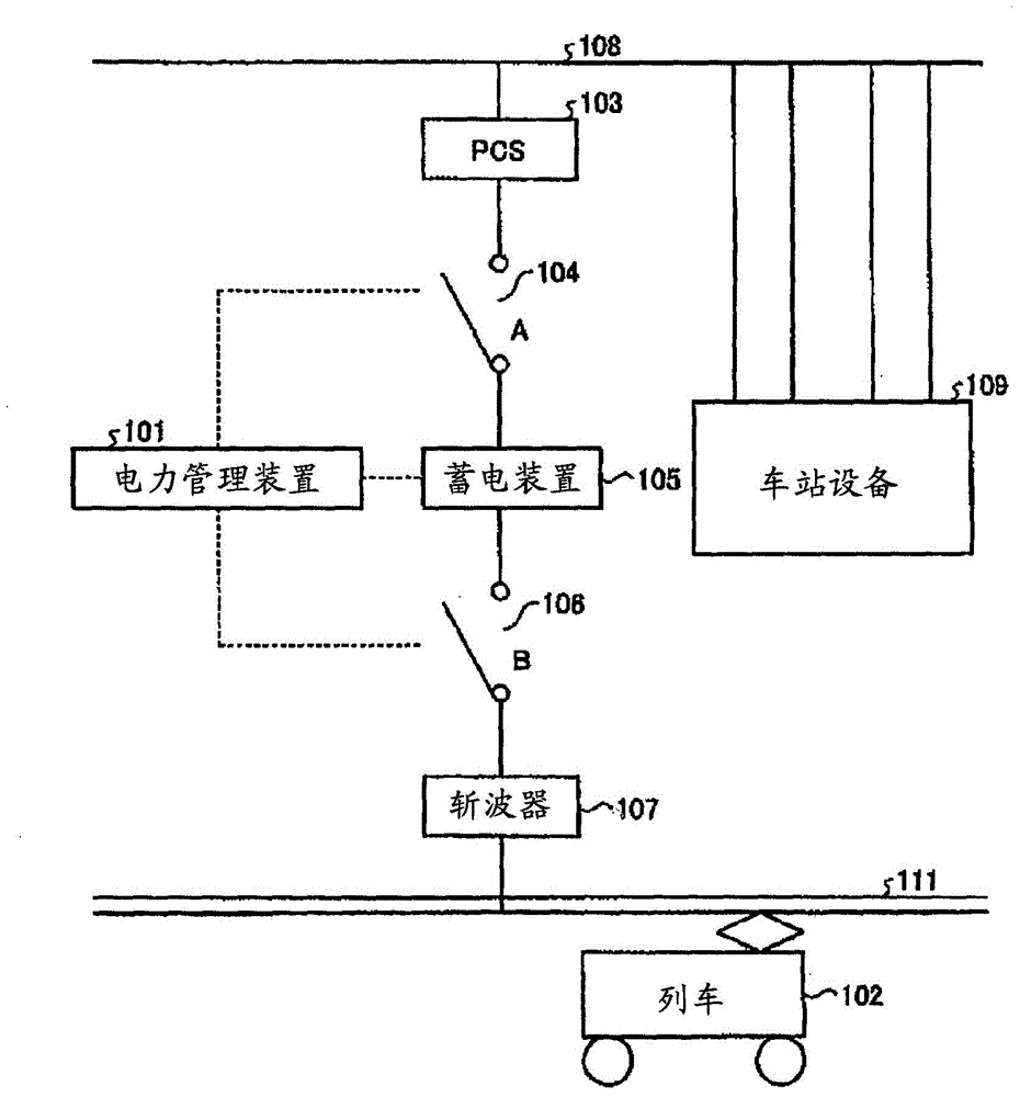
[0043] First, a station system and an electric railway system using the power management device of the first embodiment will be described in detail. figure 1 It is a diagram showing a schematic configuration of a station system and an electric railway system using the power management device according to the first embodiment.

[0044] The train 102 in the electric railway system operates using electric power supplied from the feeder 111 as a power source. Electric power is supplied to the feeder line 111 from a substation (not shown).

[0045] In the station, various station equipment 109 such as elevators, escalators, and lighting are installed.

[0046] It is conceivable to install the power storage device 105 in the station. The reason for this is that, for example, if the power storage device 105 is installed in a substation, since the substation is generally located far from the station, such as between stations, power transmission loss occurs during power storage and d...

no. 2 Embodiment approach

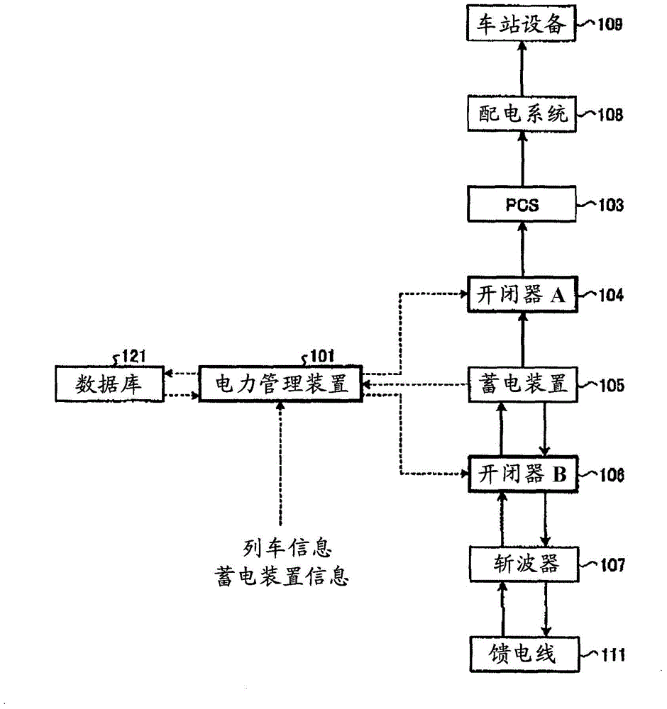
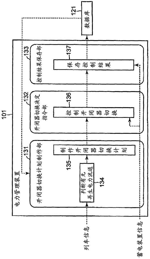
[0071] Next, a second embodiment will be described. This embodiment is an embodiment capable of coping with failures such as train accidents compared to the first embodiment. Figure 7 The power management device 101a of this embodiment, related equipment, and the flow of data and signals exchanged (dotted arrows) and the flow of power supply (solid arrows) are shown, Figure 8 The structure of the power management device 101a of this embodiment is shown. Such as Figure 7 as well as Figure 8 As shown, the basic configuration is the same as that of the first embodiment, and descriptions of the common items are omitted.

[0072] This embodiment differs from the first embodiment in that the operating information is used in the switch switching determination / instruction unit 132a. Here, the operation information refers to information including the suspension time of the train operation.

[0073] The switch switching determination / command unit 132a determines whether or not ...

no. 3 Embodiment approach

[0080] Next, a third embodiment will be described. This embodiment adopts the same configuration as the above-mentioned second embodiment, but the switch switching control processing (136) by the switch switching determination / command unit 132a is different in that the following SOC width is taken into consideration. Descriptions of items common to the above-described embodiments are omitted.

[0081] Generally, the ratio of the remaining charge of power storage device 105 to the capacity of the battery at the time of full charge is called State Of Charge (hereinafter referred to as SOC). There is an appropriate range of SOC depending on the type of power storage device 105 , and it can be said that by maintaining the SOC within the proper range, performance degradation of power storage device 105 can be prevented. Here, the suitable SOC range of power storage device 105 is referred to as SOC width.

[0082] In this embodiment, the switch switching determination / instruction ...


PUM


Abstract

[Problem] To enable a power storage device, which stores electricity such as regenerative electric power and discharges the electricity to a feeder line or a power distribution system, to perform effective charging and discharging. [Solution] A power management device according to an embodiment generates a switching plan for performing open-close switching control for a first switch and a second switch which are never closed at the same time, said first switch being provided between a power storage device and a power distribution system, and said second switch being provided between the power storage device and a feeder line. Furthermore, the power management device determines the content of the switching control for the first switch and the second switch in accordance with the generated switching plan and sends resulting commands to the first switch and the second switch. In this configuration, whether or not there will be transfer of regenerative electric power between trains up until the elapse of an arbitrary unit time is determined on the basis of train information including a train operation schedule, and a switching plan wherein the first switch is closed for the duration of the unit time is generated if there will be transfer of regenerative electric power between the trains, while a switching plan wherein the second switch is closed for the duration of the unit time is generated if there will be no transfer of regenerative electric power between the trains.

Description

[0001] Citations for Associated Applications [0002] This application is based on the benefit of priority based on the prior Japanese Patent Application No. 2012-261363 filed on November 29, 2012 and the prior Japanese Patent Application No. 2012-240758 filed on October 31, 2012, and claiming that benefit, the entire contents of which are hereby incorporated by reference. technical field [0003] This embodiment relates to a power management device and a power management system. Background technique [0004] In order to effectively utilize electric power, the coordination of energy management has been developed in various countries around the world. [0005] As one of such arrangements, there is BEMS (Building and Energy Management System: building energy management system). BEMS refers to a system for reducing energy consumption through power management of building equipment / equipment, etc. For example, it is possible to reduce the electric power of buildings and the am...

Claims


Application Information

Patent Timeline
IPC IPC(8): B60M3/06
CPCB60M3/06
Inventor 花岛由美原博纪三吉京金子博之
Owner KK TOSHIBA
Why Eureka
Try Eureka