Methods for passivating metallic implantable medical devices including radiopaque markers

A medical device and marker technology, applied in the field of manufacturing implantable medical devices, can solve the problems of no available space, increasing the wall thickness of the stent, affecting the flexibility of the stent, etc.

Inactive Publication Date: 2015-04-29
ABBOTT CARDIOVASCULAR
View PDF8 Cites 9 Cited by
  • Summary
  • Abstract
  • Description
  • Claims
  • Application Information

AI Technical Summary

Problems solved by technology

[0008] Radiopacity can be improved by increasing stent wall thickness (e.g., strut thickness), but this adversely affects stent flexibility (requires stent flexibility for ease of delivery)
Furthermore, increasing the stent wall thickness may not be acceptable from a practical point of view as there may be simply no additional space available within the desired vasculature to which the stent is to be delivered

Method used


Image

  • Methods for passivating metallic implantable medical devices including radiopaque markers
  • Methods for passivating metallic implantable medical devices including radiopaque markers
  • Methods for passivating metallic implantable medical devices including radiopaque markers

Examples


Embodiment approach

[0038] In one embodiment, the present method can achieve passivation of the stent body as well as radiopaque markers by using electropolishing rather than traditional chemical passivation techniques. For example, while electropolishing does function to remove metallic material from the electropolished structure, it also results in the formation of a thin passivating film layer (eg, an oxide of the underlying metal) on the surface of the structure. According to one embodiment, electropolishing is achieved by immersing the structure to be electropolished in an electrolyte solution and subjecting the immersed structure to an applied electrical current, causing anodic metal dissolution of the metal on the surface of the structure.

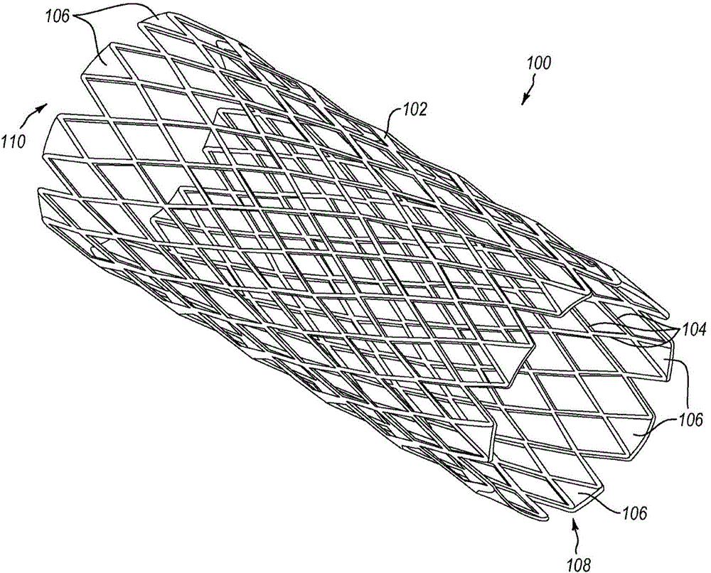
[0039] Such as image 3 As shown, according to method S10, an implantable medical device (eg, a tubular stent body) is provided at S12. Prior to attaching the radiopaque markers, a preliminary electropolishing (S14) of the device body smoothes the sur...


PUM

PropertyMeasurementUnit
thicknessaaaaaaaaaa
surface roughnessaaaaaaaaaa

Abstract

The present disclosure is directed to methods of manufacturing and passivating stents and other implantable medical devices including one or more attached radiopaque markers. In one embodiment, the method includes providing a metallic implantable medical device body without any radiopaque marker(s) attached thereto, primary electropolishing the device body without any markers attached thereto, attaching one or more radiopaque markers to the device body, and lightly electropolishing the device including device body and attached radiopaque markers. Light electropolishing removes no more than about 5 percent by weight of the device (i.e., the device body and attached marker(s)). Light electropolishing passivates the exposed surfaces of the device body and markers, while also providing electropolishing to the region of any welds where the radiopaque marker(s) attach to the device body.

Description

[0001] Cross References to Related Applications [0002] This application claims priority to US Application No. 13 / 548,908, filed July 13, 2012, the entire contents of which are incorporated herein by reference. Background technique [0003] The human body includes various lumens, such as blood vessels or other passages. The lumen may occasionally become at least partially blocked or weakened. For example, the lumen may be at least partially obstructed by a tumor, plaque, or both. An implantable stent can be used to reopen or reinforce an at least partially blocked lumen. [0004] A stent is usually a tubular body that is placed in a lumen of the body. When delivering the stent to the desired deployment site in the body, the stent can be delivered into the body through a catheter that supports the stent in a reduced size configuration. At the deployment site, the stent is expandable such that, for example, the stent contacts the lumen wall to dilate the lumen. [0005] Th...

Claims


Application Information

Patent Timeline
Patent Type & Authority Applications(China)
IPC IPC(8): C25F3/18C25F3/16A61F2/91
CPCC25F3/16A61F2240/001A61F2250/0054A61F2250/0098F04C2270/041A61F2210/0076A61F2/86A61L31/022A61L31/18
Inventor 林志诚
Owner ABBOTT CARDIOVASCULAR
Why Eureka
Try Eureka