
Ultra-dry filtering machine and filtrating method thereof

A filtration method and filter technology, applied in the directions of filtration and separation, separation methods, chemical instruments and methods, can solve the problems of low degree of automation, affecting the strength of the cylinder body, low work efficiency, etc., to improve the level of automation and improve desliming. Effects, effects with a simple structure

Active Publication Date: 2015-05-06
YANGZHOU RONGHENG MACHINERY MFG CO LTD
View PDF8 Cites 9 Cited by
  • Summary
  • Abstract
  • Description
  • Claims
  • Application Information

AI Technical Summary

Problems solved by technology

The application number is: 201110078673.5 discloses a high-dryness filter and method, although the solid moisture content of the filter can reach within 60%, there are still defects that can be improved: 1. The water inlet on the cylinder body is directly arranged on the On the cylinder body, the strength of the cylinder body is affected, and the service life is shortened; 2. The method used leads to uneven dryness of the filter residue, the filter cloth is easy to plug, and it is difficult to clean. The filter residue is closely adhered to the filter cloth and other structures after high pressure. Desliming is difficult
Unable to achieve automatic desliming, resulting in low work efficiency; 3. Low degree of automation and low efficiency; 4. The dryness of the filter residue is not stable

Method used


Image

  • Ultra-dry filtering machine and filtrating method thereof
  • Ultra-dry filtering machine and filtrating method thereof
  • Ultra-dry filtering machine and filtrating method thereof

Examples


Embodiment Construction

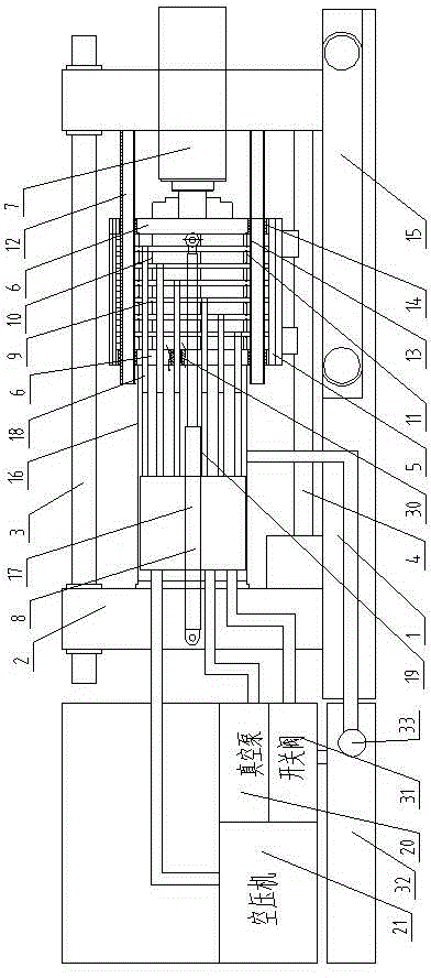
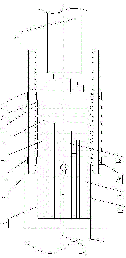
[0031] Such as figure 1 , 2 , 3, the present invention includes a bed 1, the left and right sides of the bed 1 are respectively provided with walls 2, the walls 2 on both sides are connected by pull rods 3, and the bed 1 is provided with horizontally arranged slides. Rail 4, the top of slide rail 4 is provided with cylinder body 5, and the bottom of cylinder body 5 is slidably installed on the slide rail 4 by slide block, and the below of cylinder body 5 is provided with belt conveyor 15.

[0032] Pistons 6 are respectively arranged on the left and right sides of the cylinder body 5, and the piston 6 on the left side is connected to the wall body 2 on the left side through a hollow cantilever 16. A sealed transfer box 17 is fixed in the cavity of the cantilever 16, and the cylinder body 5 The wall body 2 on the right side is connected with the first hydraulic cylinder 7, the piston 6 on the right side is connected with the hydraulic rod of the first hydraulic cylinder 7, the ...


PUM


Abstract

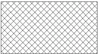
The invention relates to an ultra-dry filtering machine and a filtrating method thereof. The ultra-dry filtering machine comprises a bed body and walls respectively arranged at the left side and the right side of the bed body. According to the invention, a slide track is laterally arranged on the bed body; a cylinder is arranged above the slide track; the bottom of the cylinder is installed on the slide track via a sliding block in a sliding way; pistons are respectively arranged on the left side and the right side in the cylinder; the left piston is connected with the left wall; a first hydraulic cylinder is connected to the right wall of the cylinder; the right piston is connected with a hydraulic rod of the first hydraulic cylinder; multiple filtering plates are axially distributed inside the cylinder; mud-cutting mechanisms are arranged between the filtering plates on two sides and the pistons on corresponding sides and between adjacent filtering plates. According to the invention, a mud-cutting net is arranged between the filtering plates, so as to enlarge gaps between the filtering plates while triggering the mud-cutting net to cut off solids between the filtering plates, thus solving the difficulty of mud removing of the prior art.

Description

technical field [0001] The invention relates to an ultra-high dryness filter and a filtering method. Background technique [0002] The main function of the filter press is to separate the solid-liquid mixture. The more thorough the separation, the lower the moisture content of the solid produced, the better the effect. The application number is: 201110078673.5 discloses a high-dryness filter and method, although the solid moisture content of the filter can reach within 60%, there are still defects that can be improved: 1. The water inlet on the cylinder body is directly arranged on the On the cylinder body, the strength of the cylinder body is affected, and the service life is shortened; 2. The method used leads to uneven dryness of the filter residue, the filter cloth is easy to plug, and it is difficult to clean. The filter residue is closely adhered to the filter cloth and other structures after high pressure. Difficult to remove mud. Unable to achieve automatic des...

Claims


Application Information

Patent Timeline
IPC IPC(8): B01D25/12B01D25/32B01D25/34B01D37/00
Inventor 丁志春
Owner YANGZHOU RONGHENG MACHINERY MFG CO LTD
Learn More