
Reed suspension structure for standard vibrating table

A vibrating table and reed technology, which is applied to fluids, measuring devices, and instruments that utilize vibration, can solve the problems of high machining accuracy requirements for parts, large distortion of the vibrating table, and poor linear characteristics, and reduce manufacturing costs. Cost, improved accuracy, simple structure effect

Active Publication Date: 2015-05-06
ZHEJIANG UNIV
View PDF5 Cites 10 Cited by
  • Summary
  • Abstract
  • Description
  • Claims
  • Application Information

AI Technical Summary

Problems solved by technology

[0003] Traditional standard vibration tables mostly use air-floating guide rails and ordinary mechanical springs as the guiding and supporting mechanisms for moving parts. In order to ensure that the air-floating guide rails have sufficiently good guiding characteristics, the machining accuracy of the parts is required to be high, and the cost is expensive. Ordinary mechanical springs have poor linear characteristics, resulting in large distortion of the output waveform of the vibrating table

Method used


Image

  • Reed suspension structure for standard vibrating table
  • Reed suspension structure for standard vibrating table
  • Reed suspension structure for standard vibrating table

Examples


Embodiment Construction

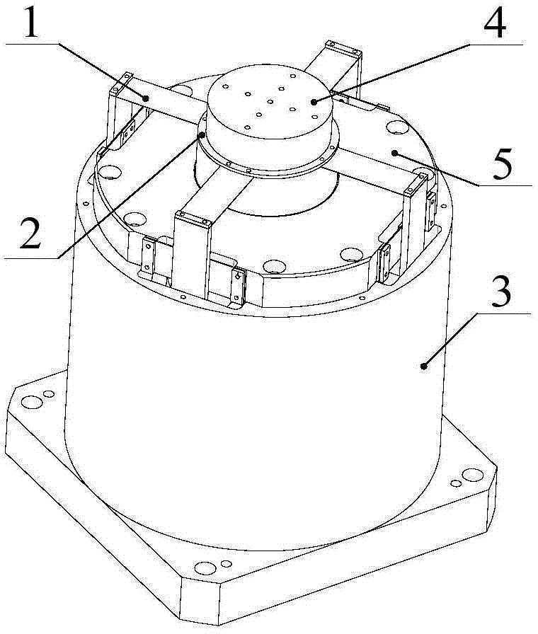
[0022] Such as figure 1 As shown, the reed suspension structure for a standard vibrating table includes four sets of reed suspension units 1 and a connecting ring 2 connecting the reed suspension unit 1 and the moving part 4 of the vibrating table 3, and the connecting ring 2 is fixed on the vibrating On the moving part 4 of the table 3, the connecting ring 2 is coaxial with the moving part 4 of the vibrating table 3;

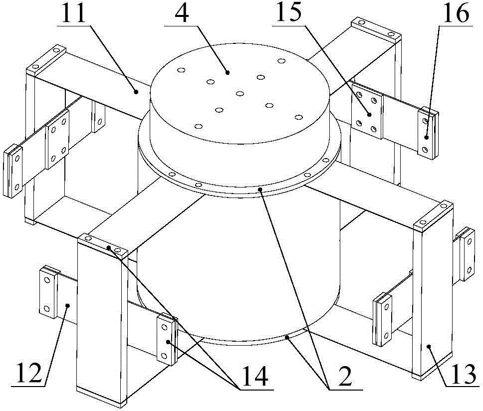
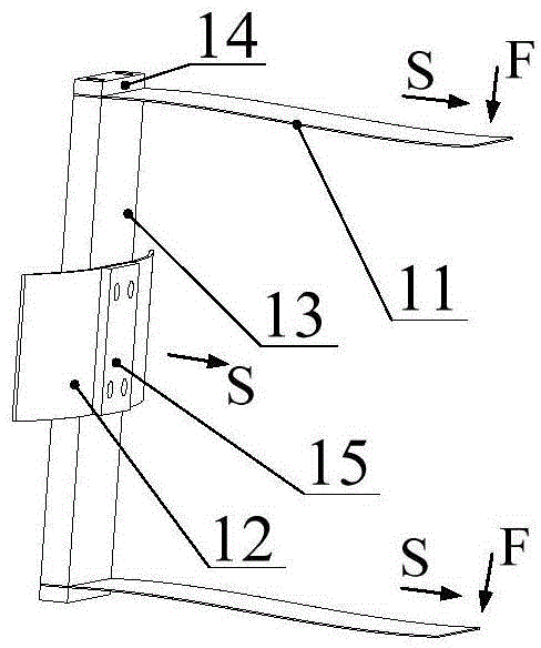
[0023] to combine figure 2 , each reed suspension unit 1 includes a pair of horizontal reeds 11, a reed support block 13 and a side reed 12; a pair of horizontal reeds 11 are respectively fixed to the two ends of the reed support block 13, The other end of the horizontal reed 11 is fixed on the connecting ring 2, and the reed support block 13 is arranged axially along the moving part 4 of the vibrating table 3; the side reed 12 is fixed on the reed support block 13, and the side reed 12 and the spring The sheet support block 13 is orthogonal, and the two end...


PUM


Abstract

The invention relates to a reed suspension structure for a standard vibrating table. The reed suspension structure comprises a plurality of reed suspension units, and connecting rings which are used for connecting the reed suspension units and a moving component of the vibrating table; the connecting rings are fixed onto the moving component of the vibrating table and are coaxial with the moving component of the vibrating table; each reed suspension unit comprises a pair of horizontal reeds, reed support block and lateral reed; each pair of horizontal reeds are respectively fixed on two ends of the corresponding reed support block; the other end of each horizontal reed is fixed on the corresponding connecting ring; each reed support block is axially arranged along the vibrating table; each lateral reed is fixed on the corresponding reed support block and is orthogonal to the corresponding reed support block; two ends of each lateral reed are fixed relative to a pedestal of the vibrating table; a space allowing each lateral reed to radially deform along the vibrating table is formed between each lateral reed and the vibrating table; when the moving component of the vibrating table vibrates, each reed suspension unit is uniformly stressed. The reed suspension structure has the advantage that accurate orientation and linear support are simultaneously realized for the moving component of the standard vibrating table.

Description

technical field [0001] The invention relates to a reed suspension structure applicable to a standard vibrating table. technical background [0002] Vibration sensors are the main way to obtain various vibration signals, and are widely used in many fields of human production and life. In order for the vibration sensor to convert the mechanical vibration signal into an electrical signal more accurately, so as to facilitate the detection, analysis and storage of the signal, the vibration sensor must be calibrated accurately to ensure the accuracy of the obtained vibration signal. Therefore, it is of great significance to establish a vibration calibration system, and the standard vibration table is the core of the entire vibration calibration system, and the quality and cost of its output vibration excitation signal are directly related to the calibration accuracy and manufacturing cost of the vibration calibration system. [0003] Traditional standard vibration tables mostly u...

Claims


Application Information

Patent Timeline
Patent Type & Authority Applications(China)
IPC IPC(8): B06B1/14G01H17/00
Inventor 何闻张旭飞贾叔仕周杰
Owner ZHEJIANG UNIV
Learn More