Cutting and chamfering control device and pipe cutting machine

A technology of control device and pipe cutting machine, which is applied in shearing device, feeding device, positioning device, etc., can solve the problem that the chamfering accuracy needs to be improved, and achieve the effect of improving production efficiency

Active Publication Date: 2015-05-06
柳燕明
View PDF8 Cites 4 Cited by
  • Summary
  • Abstract
  • Description
  • Claims
  • Application Information

AI Technical Summary

Problems solved by technology

[0015] The applicant designed the patent number: ZL201320588694.6 for the processing of small-diameter material tubes, and the title of the invention is: "Cutting and chamfering integrated turning tool and a pipe cutting machine for cutting and chamfering in one clamping", which can be installed in one time. clip, multi-section cutting, and can further chamfer the inner and outer edges of the two ends of the cut, which improves the production efficiency and product quality, but still needs to solve the problem of cutting large diameter and long size material pipes. Accuracy control also needs to be improved

Method used


Image

  • Cutting and chamfering control device and pipe cutting machine
  • Cutting and chamfering control device and pipe cutting machine
  • Cutting and chamfering control device and pipe cutting machine

Examples


Embodiment Construction

[0075] Embodiments of the present invention will be further described below in conjunction with the accompanying drawings.

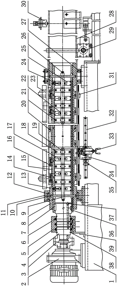
[0076] Such as figure 1As shown, the pipe cutting machine includes a machine base 1, a motor reducer 2 fixedly installed on the machine base 1, and a frequency conversion speed regulating motor can also be directly used, and the number of revolutions of the motor reducer is between 50 and 1000 rpm. The motor reducer 2 is connected to the mandrel 4 through the coupling 3, the right side of the mandrel 4 is connected to the main shaft tube 8 through the key 7 and fixed, the left end of the main shaft tube 8 is provided with a shaft support seat 11, and the outer periphery of the main shaft tube 8 is provided with a material tube for fastening device, the material tube 28 is set on the material tube fastening device, the right end of the main shaft tube 8 is provided with a shaft end bearing assembly 27 supporting the material tube 28, and the rear side of ...


PUM


Abstract

The invention relates to a cutting and chamfering control device and a pipe cutting machine, in particular to the cutting and chamfering control device used for cutting and chamfering thin-wall round pipes and the pipe cutting machine used for installing, clamping and cutting a plurality of thin-wall round pipes in one step. The cutting and chamfering control device comprises a linear guide rail and a cutting and chamfering assembly, wherein the cutting and chamfering assembly is glidingly arranged on the linear guide rail, and is connected with a chambering control assembly, the chambering control assembly comprises a support frame which is provided with a vertical plate and is fixedly arranged on the cutting and chamfering assembly, an axially fixed and rotatable screw rod is arranged on the vertical plate, a regulating handle is fixedly arranged on the screw rod, the screw rod pulls the vertical plate, and one end of the screw rod can slide relative to the linear guide rail and is connected with a stop support rod assembly through screw threads. The pipe cutting machine comprises at least one group of cutting and chambering control devices. On the basis of meeting the material pipe cutting requirements, the precision of inner and outer edge chambering of the two end surfaces of cut openings can be precisely controlled, the requirement of installing, clamping and cutting a plurality of large-pipe-diameter and long-dimension materials pipes in one step is met, and in addition, the roundness of the cut material pipes can be ensured.

Description

technical field [0001] The invention relates to a cutting and chamfering control device and a pipe cutting machine, in particular to a cutting and chamfering control device for cutting and chamfering thin-walled round pipes and a pipe cutting machine for cutting multiple thin-walled round pipes in one clamp. Background technique [0002] In industrial production, after the thin-walled round tube is cut, it is also required to chamfer the inner and outer edges of the two ends of the cut. At the same time, it is also required that the roundness accuracy of the material tube should not be damaged during the process of clamping the round tube. At present, the traditional tube cutting Processing mainly has the following five processing methods. [0003] 1. Lathe cutting and chamfering processing method: [0004] The outer diameter or inner diameter of the round pipe is clamped by the chuck of the lathe. When the pipe wall is about to be cut off, the material pipe often swings gr...

Claims


Application Information

Patent Timeline
Patent Type & Authority Applications(China)
IPC IPC(8): B23B5/14B23B5/16B23B15/00B23B27/04
CPCB21D43/026B23D21/006B23D33/02B23D33/12
Inventor 柳燕明王磊陈律行
Owner 柳燕明
Why Eureka
Try Eureka