Method for recognizing synchronous reflection point position in compact field antenna measurement

A technology of synchronous reflection and antenna measurement, which can be used in antenna radiation patterns, special data processing applications, instruments, etc., and can solve problems such as inability to eliminate

Inactive Publication Date: 2015-05-06
BEIJING INST OF RADIO METROLOGY & MEASUREMENT
View PDF3 Cites 14 Cited by
  • Summary
  • Abstract
  • Description
  • Claims
  • Application Information

AI Technical Summary

Problems solved by technology

However, this processing method cannot eliminate the reflected signal of the transmitted wave of the compact field feed source in the compact field, which is reflected by the reflection point in the compact field and reaches the antenna under test, and the signal transmitted by the compact field feed source after being converted by the reflection surface of the compact field and then reaches the test antenna. The interfering reflected signal with the same time as the direct plane wave signal of the antenna, that is, if the reflected signal is time-synchronized with the direct wave signal, it cannot be eliminated by the existing time-domain gating method

Method used


Image

  • Method for recognizing synchronous reflection point position in compact field antenna measurement
  • Method for recognizing synchronous reflection point position in compact field antenna measurement
  • Method for recognizing synchronous reflection point position in compact field antenna measurement

Examples


Embodiment Construction

[0035] In order to illustrate the present invention more clearly, the present invention will be further described below in conjunction with preferred embodiments and accompanying drawings. Similar parts in the figures are denoted by the same reference numerals. Those skilled in the art should understand that the content specifically described below is illustrative rather than restrictive, and should not limit the protection scope of the present invention.

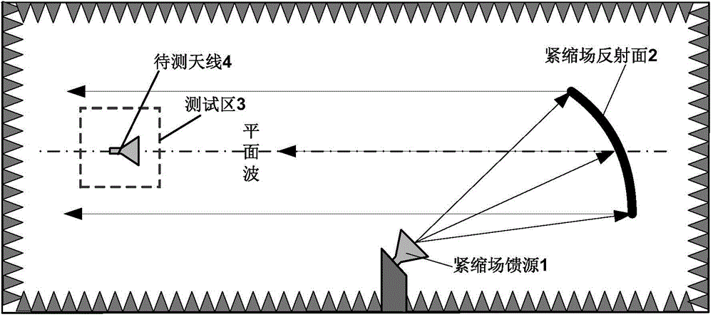
[0036] The invention discloses a method for identifying the position of a synchronous reflection point measured by a compact field antenna. The steps of the method include:

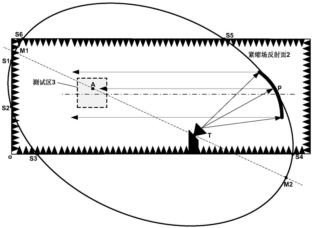
[0037] Establish a three-dimensional compact field darkroom geometric model space Cartesian coordinate system; the three-dimensional rectangular coordinate system takes any corner of the compact field darkroom as the origin O of the coordinate system, takes the length direction as the X axis, takes the width direction as the Y axis, and takes the heigh...


PUM


Abstract

The invention discloses a method for recognizing a synchronous reflection point position in the compact field antenna measurement. The method comprises the steps of building a three-dimensional rectangular coordinate system in a dark chamber of a compact field; determining the position of a compact field feed source in the three-dimensional rectangular coordinate system; determining the position of the compact field reflecting surface according to the position of the compact field feed source and the position of a testing area; building an ellipsoidal surface in the compact field dark chamber by using the position of the compact field feed source and the position of an antenna to be measured, in the testing area as the focuses and the length of the transmission path of the compact field feed source from the reflecting surface to the antenna to be measured, at any position in the testing area, wherein the part in which the ellipsoidal surface is intersected with each surface of the compact field dark chamber and an object in an inner space of the compact field dark chamber is the position of a synchronous reflecting point. With the adoption of the method, the position of the synchronous reflecting point that a reflecting signal and a direct wave signal in a compact field synchronously reaches a receiving antenna.

Description

technical field [0001] The invention relates to a method for identifying the position of a reflection point, in particular to a method for identifying a position of a synchronous reflection point for measurement of a compact field antenna. Background technique [0002] With the development of antenna measurement technology, the requirements for the measurement accuracy of antenna electromagnetic characteristics are getting higher and higher. The compact field can provide the plane wave environment required for antenna measurement within a short distance, and has become a common method for antenna measurement. The layout diagram of the compact field antenna measurement system is as follows: figure 1 As shown in the figure, the compact field feeder emits a spherical wave, irradiates the compact field reflecting surface, and is converted into a plane wave after reflection, and the antenna under test in the test area receives the plane wave. The test area is the area with the ...

Claims


Application Information

Patent Timeline
Patent Type & Authority Applications(China)
IPC IPC(8): G01R29/10G06F19/00
Inventor 马永光韩玉峰钱冰华高启轩
Owner BEIJING INST OF RADIO METROLOGY & MEASUREMENT
Why Eureka
Try Eureka