Capacitor testing device and capacitor testing method

A testing device and capacitor technology, applied in the field of capacitors, can solve the problem of inability to record the power-on test time, voltage drop, current, inductance, DC resistance and reactance temperature historical data of the capacitor under test, and inability to generate a very intuitive capacitance performance curve graph. Qualified products output alarm and other problems to achieve the effect of eliminating resonance, eliminating influence and improving the pass rate

Inactive Publication Date: 2015-05-06
南通富士特电力自动化有限公司
View PDF10 Cites 9 Cited by
  • Summary
  • Abstract
  • Description
  • Claims
  • Application Information

AI Technical Summary

Problems solved by technology

[0002] When traditional capacitors are tested, they generally only record the voltage value, current value, and capacitance value, and cannot record historical data such as the power-on test time, voltage

Method used


Image

  • Capacitor testing device and capacitor testing method
  • Capacitor testing device and capacitor testing method
  • Capacitor testing device and capacitor testing method

Examples


Embodiment 1

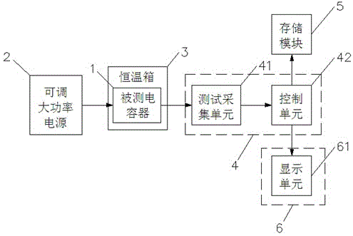
[0045] see figure 1 , as shown in the legend therein, a capacitor testing device for performance testing of the capacitor under test 1, including:

[0046] A power supply module, including an adjustable high-power power supply 2, the adjustable high-power power supply 2 is connected to the capacitor under test 1 and provides a working voltage for the capacitor under test 1;

[0047] A constant temperature box 3, the temperature of which is adjustable and used to place the measured capacitor 1;

[0048] A test module 4 includes a test acquisition unit 41 and a control unit 42, the test acquisition unit 41 connects the capacitor under test 1 and collects the voltage value, current value and temperature value of a plurality of groups of capacitor under test 1; the control unit 42 connects the test acquisition The unit 41 receives and calculates the capacity values ​​of multiple sets of measured capacitors 1, and draws the temperature characteristic curve, withstand voltage chara...

Embodiment 2

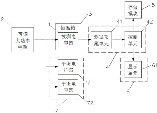
[0073] see figure 2 , as shown in the legend therein, the rest are the same as the first embodiment, the difference is that the above-mentioned test device also includes a current for eliminating the influence of the action of the capacitor under test 1 on the adjustable high-power power supply 2 The balance module 7 , the current balance module 7 includes a balance reactor 71 and a balance capacitor 72 , the balance reactor 71 and the balance capacitor 72 are respectively arranged in parallel with the measured capacitor 1 and connected to the adjustable high-power power supply 2 .

[0074] By setting the balance reactor 71 and the balance capacitor 72, the system current can be balanced, resonance can be eliminated, and the influence of the action of the measured capacitor 1 on the adjustable high-power power supply 2 can be eliminated.

Embodiment 3

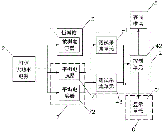
[0076] see image 3 , as shown in the legend therein, the rest are the same as those in Embodiment 2, the difference is that the test module 4 also includes a monitoring acquisition unit 43, and the monitoring acquisition unit 43 is respectively connected to the adjustable high-power power supply 2 and the balance reactor 71 And balance capacitor 72 and collect the voltage value, current value and temperature value of adjustable high-power power supply 2, balance reactor 71 and balance capacitor 72; Control unit 42 connects monitoring acquisition unit 43 and receives adjustable high-power power supply 2, balance reactance The voltage value, current value and temperature value of the reactor 71 and the balance capacitor 72; the display unit 61 is connected to the control unit 42 and displays the voltage value, current value and temperature value of the adjustable high-power power supply 2, the balance reactor 71 and the balance capacitor 72.

[0077] By arranging the monitoring...


PUM


Abstract

The invention discloses a capacitor testing device used for testing the performance of a to-be-tested capacitor. The capacitor testing device comprises a power supply module including an adjustable high-power power supply, a testing module including a testing collection unit and a control unit, a storage module connected with the control unit, and a man-machine interaction module including a display unit. By arranging the testing collection unit, the control unit, the storage unit and the display unit, complete record and effective comparison of related performance indexes of the to-be-tested capacitor and more user-friendly man-machine interaction can be realized. Finally, the performance of the to-be-tested capacitor can be analyzed based on a temperature characteristic curve, a voltage withstanding characteristic curve and an attenuation characteristic curve graph drawn by the control unit, and the first-pass yield of capacitors can be improved in an automatic way. The invention further discloses a capacitor testing method.

Description

technical field [0001] The invention relates to the field of capacitors, in particular to a capacitor testing device and a testing method thereof. Background technique [0002] When traditional capacitors are tested, they generally only record the voltage value, current value, and capacitance value, and cannot record historical data such as the power-on test time, voltage drop, current, inductance, DC resistance, and reactance temperature of the capacitor under test, and cannot produce very intuitive Capacitance performance curve and output alarm for unqualified products. Contents of the invention [0003] In order to solve the above problems, the present invention provides a capacitor testing device capable of completely recording relevant performance indicators of the capacitor under test, effective comparison and more humanized man-machine dialogue. [0004] The technical scheme of the present invention is as follows: a test device for a capacitor, used for performan...

Claims


Application Information

Patent Timeline
IPC IPC(8): G01R31/02G01R31/12
Inventor 张澎张劲
Owner 南通富士特电力自动化有限公司
Why Eureka
Try Eureka