
Liquid crystal display panel and manufacturing method thereof

A technology of a liquid crystal display panel and a manufacturing method, which are applied in the directions of instruments, nonlinear optics, optics, etc., can solve the problems of reducing the aperture ratio of pixels, etc., and achieve the effect of improving the display effect.

Active Publication Date: 2015-05-06
TCL CHINA STAR OPTOELECTRONICS TECH CO LTD
View PDF5 Cites 4 Cited by
  • Summary
  • Abstract
  • Description
  • Claims
  • Application Information

AI Technical Summary

Problems solved by technology

[0005] The object of the present invention is to provide a liquid crystal display panel and a manufacturing method thereof, so as to solve the technical problem of reducing the aperture ratio of pixels when the existing display panel solves the problem of large viewing angle deviation

Method used


Image

  • Liquid crystal display panel and manufacturing method thereof
  • Liquid crystal display panel and manufacturing method thereof
  • Liquid crystal display panel and manufacturing method thereof

Examples


Embodiment Construction

[0037] The following descriptions of the various embodiments refer to the accompanying drawings to illustrate specific embodiments in which the present invention can be practiced. The directional terms mentioned in the present invention, such as "up", "down", "front", "back", "left", "right", "inside", "outside", "side", etc., are for reference only The orientation of the attached schema. Therefore, the directional terms used are used to illustrate and understand the present invention, but not to limit the present invention. In the figures, structurally similar units are denoted by the same reference numerals.

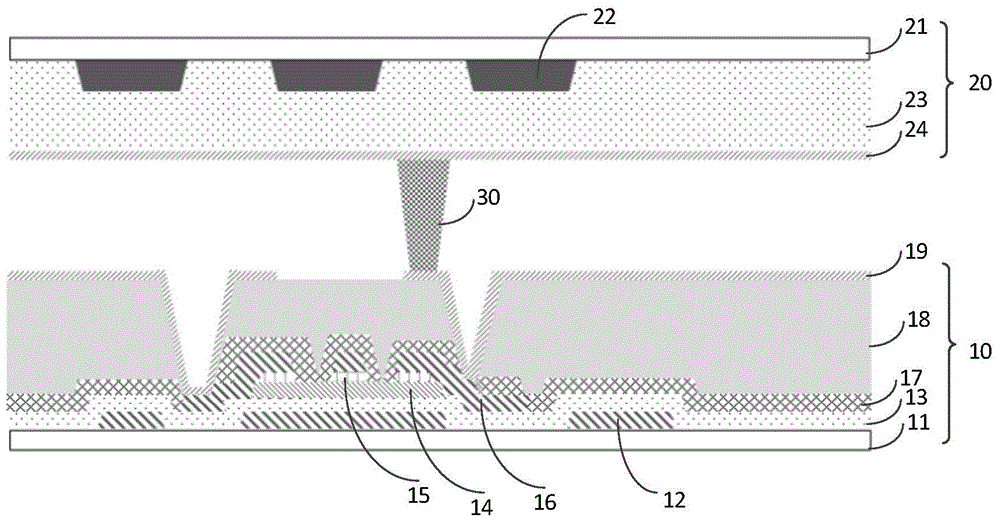
[0038] Please refer to figure 1 , figure 1 It is a structural schematic diagram of a liquid crystal display panel in the prior art;

[0039] The existing liquid crystal display panel includes a first substrate 20, a second substrate 10, a liquid crystal layer, and a spacer 30; the first substrate 20 includes a base substrate 21, a black matrix layer 22 and a flat l...


PUM


Abstract

The invention provides a liquid crystal display panel and a manufacturing method thereof. The manufacturing method comprises the following steps of respectively manufacturing a first substrate and a second substrate, wherein the second substrate corresponds to the first substrate; filling liquid crystals between the first substrate and the second substrate; when the first substrate or the second substrate is being manufactured, enabling a first distance to be greater than a second distance, wherein the first distance is the distance between a second transparent conductive layer corresponding to a main pixel area and a first transparent conductive layer, and the second distance is the distance between a second transparent conductive layer corresponding to a sub-pixel area and the first transparent conductive layer. The liquid crystal display panel and the manufacturing method thereof have the advantage that while the problem of color offset due to large view angle is solved, the opening rate of pixels is increased.

Description

【Technical field】 [0001] The invention relates to the technical field of liquid crystal displays, in particular to a liquid crystal display panel and a manufacturing method thereof. 【Background technique】 [0002] The current COA (Color Filter on Array) technology is to directly make the color-resist layer on the array substrate, which can effectively improve the requirements for the accuracy of the bonding position between the array substrate and the color filter, and at the same time reduce the cost of purchased color filters. the cost of. At the same time, because the film thickness of the color filter color resistor is much thicker than that of the array substrate side, it can reduce parasitic capacitance and effectively reduce the resistance-capacitance delay of the product, so it is widely used in large-scale products. [0003] In the large-size vertically oriented display mode, the color shift phenomenon is more serious. In order to improve the color shift phenomeno...

Claims


Application Information

Patent Timeline
Patent Type & Authority Applications(China)
IPC IPC(8): G02F1/1333
CPCG02F1/1333G02F1/133351G02F1/133512G02F1/136286G02F1/133371G02F1/134345G02F1/136222G02F1/1341G02F1/134309G02F1/13624G02F1/1368G02F2201/121G02F2201/123G02F2201/40
Inventor 王聪陈彩琴
Owner TCL CHINA STAR OPTOELECTRONICS TECH CO LTD
Learn More