Circularly polarized anti-metal tag antenna

An anti-metal tag and circular polarization technology, which is applied in the field of radio frequency identification, can solve the problems of polarization mismatch between the reader antenna and the tag antenna, the lack of circularly polarized anti-metal tag antennas, and the inconvenience of implementation and control. The idea is simple and clear, the effect of good circular polarization characteristics and good impedance characteristics

Inactive Publication Date: 2015-05-06
XIDIAN UNIV
View PDF7 Cites 13 Cited by
  • Summary
  • Abstract
  • Description
  • Claims
  • Application Information

AI Technical Summary

Problems solved by technology

In most RFID systems, the reader antenna uses a circularly polarized antenna. If the tag antenna uses a linearly polarized antenna, it will cause a polarization mismatch between the reader antenna and the tag antenna, thereby reducing the system reliability. Maximum read range achieved
It should be noted that if the reader antenna is in the form of a linearly polarized antenna, in order to ensure the maximum reading range, more s

Method used


Image

  • Circularly polarized anti-metal tag antenna
  • Circularly polarized anti-metal tag antenna
  • Circularly polarized anti-metal tag antenna

Examples


Embodiment Construction

[0027] The present invention will be further described below in conjunction with the accompanying drawings. It should be noted that this embodiment is based on the technical solution and provides detailed implementation and specific operation process, but the protection scope of the present invention is not limited to this embodiment. example.

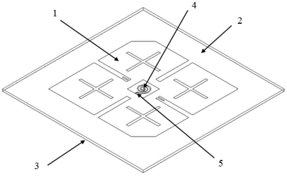
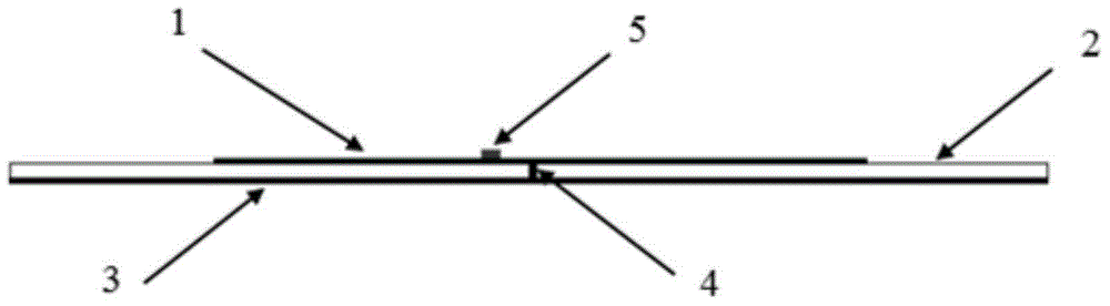
[0028] Such as figure 2 , image 3 As shown, a circularly polarized anti-metal tag antenna includes a circularly polarized radiation patch 1, a dielectric plate 2, and a metal floor 3. The circularly polarized radiation patch 1 is etched on the dielectric plate 2 by photolithography , the metal floor 3 is etched on the bottom of the dielectric board 2 by photolithography. The circularly polarized radiation patch 1 , the dielectric plate 2 and the metal floor 3 are mainly composed of high-frequency microwave dielectric plates.

[0029] Such as Figure 4 As shown, the circularly polarized radiation patch 1 is a rectangular microstri...


PUM


Abstract

The invention discloses a circularly polarized anti-metal tag antenna. The circularly polarized anti-metal tag antenna comprises a dielectric slab, and a circularly polarized radiation patch and a metal floor which are respectively etched at the top and the bottom of the dielectric slab through a light etching technology, wherein the circularly polarized radiation patch is a corner cutting rectangle micro strip patch, at least on cross-line-shaped groove which extends towards the center of the corner cutting rectangle micro strip patch is arranged on each edge of the corner cutting rectangle micro strip patch, at least one cross groove is formed in the surface of a portion surrounded by each two adjacent cross-line-shaped grooves and the corresponding edge of the circularly polarized radiation patch, a groove body is arranged at the center of the circularly polarized radiation patch, an impedance matching wire is arranged in the circularly polarized radiation patch, an impedance matching branch node is arranged at one end of each cross-line-shaped groove, close to the groove body, and the impedance matching wire is connected with the circularly polarized radiation patch through a chip, and connected with the metal floor through a metal short circuit pin. The circularly polarized anti-metal tag antenna has a good impedance characteristic and a circular polarization characteristic, is compact in structure, and simple and clear in design thought, and can be directly installed on an object of a metal structure for use.

Description

technical field [0001] The invention relates to the field of radio frequency identification, in particular to a circular polarization anti-metal tag antenna. Background technique [0002] Radio frequency identification (RFID) conducts non-contact two-way communication through electromagnetic or inductive coupling to realize automatic identification, and has the advantages of high precision and strong environmental adaptability. The development of RFID technology has promoted the advancement of antenna design and manufacturing technology, especially in the field of electronic tag antennas, which has formed a unique research field. The importance of the antenna as a device for sending and receiving carrier information in the RFID system is self-evident. [0003] In order to reduce costs, the tag antenna is directly connected to the tag chip without using matching circuits and other components between the chip and the antenna. The performance of the tag antenna and the power ...

Claims


Application Information

Patent Timeline
IPC IPC(8): H01Q1/38H01Q1/48H01Q13/08H01Q15/24H01Q1/22
Inventor 徐云学龚书喜刘英王兴张鹏飞
Owner XIDIAN UNIV
Why Eureka
Try Eureka