Wireless power transmission device with sidesway adaptability and rotation adaptability

A technology of wireless power transmission and adaptability, applied in the direction of circuit devices, circuits, inductors, etc., can solve the problem of low transmission performance

Inactive Publication Date: 2015-05-06
HARBIN INST OF TECH
View PDF7 Cites 23 Cited by
  • Summary
  • Abstract
  • Description
  • Claims
  • Application Information

AI Technical Summary

Problems solved by technology

[0004] The purpose of the present invention is to solve the problem that the existing wireless power transmission technology is limited by the position and angle of the receiving end, and the transmission performance is low, and to provide a wireless power transmission device with side shift adaptability and rotation adaptability

Method used


Image

  • Wireless power transmission device with sidesway adaptability and rotation adaptability
  • Wireless power transmission device with sidesway adaptability and rotation adaptability
  • Wireless power transmission device with sidesway adaptability and rotation adaptability

Examples


specific Embodiment approach 1

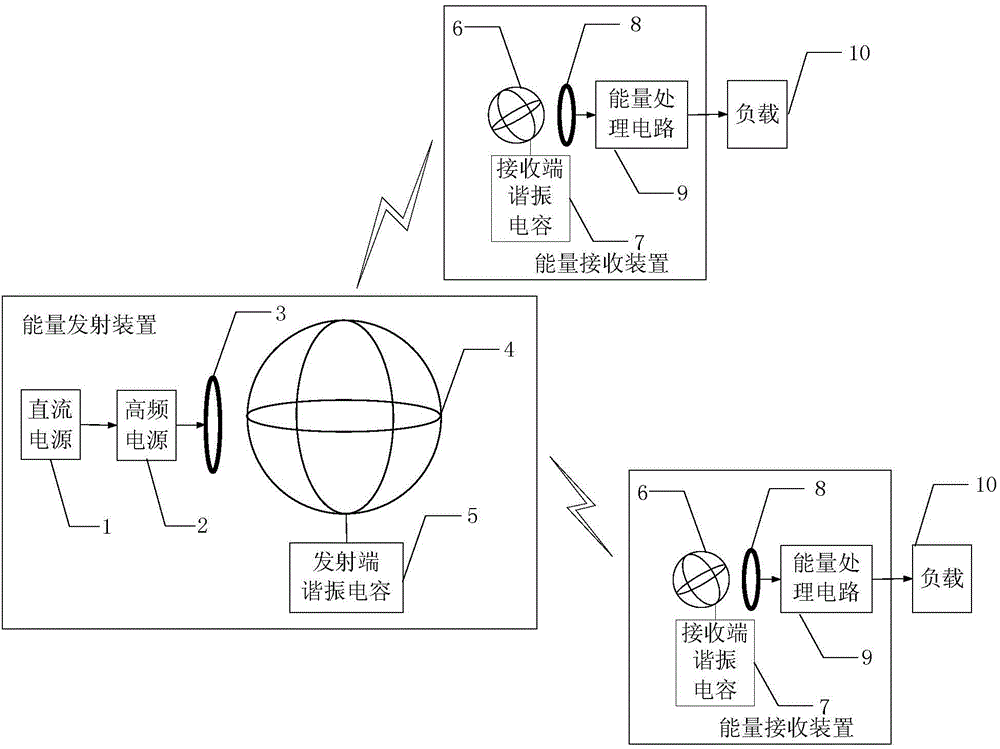
[0022] Specific implementation mode one: the following combination figure 1 Describe this embodiment mode, a wireless power transmission device with side shift adaptability and rotation adaptability described in this embodiment mode, which includes an energy transmitting device and a plurality of energy receiving devices; the energy transmitting device converts electrical energy into high-frequency changes Magnetic field, multiple energy receiving devices convert the magnetic field received in space into electric energy and then charge the load 10; the relative position between the receiving end and the transmitting end can be changed freely;

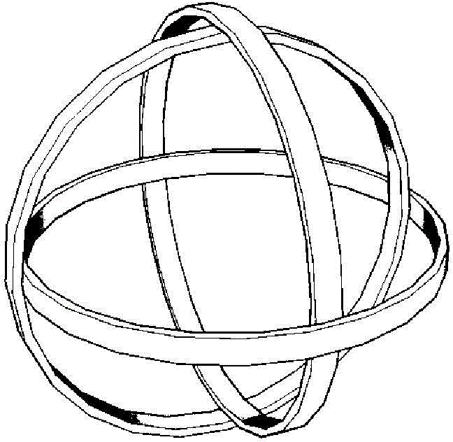
[0023] The energy transmitting device includes a DC power supply 1, a high-frequency power supply 2, an energy excitation coil 3, an energy transmitting coil 4 and a resonant capacitor 5 at the transmitting end, the DC power supply 1 outputs current to the high-frequency power supply 2, and the high-frequency power supply 2 converts the ...

specific Embodiment approach 2

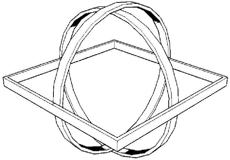
[0031] Embodiment 2: This embodiment will further explain Embodiment 1. The three planar coils that constitute the energy transmitting coil 4 or the energy receiving coil 6 are all connected in series, parallel or mixed connection through taps. .

specific Embodiment approach 3

[0032] Embodiment 3: This embodiment further describes Embodiment 1. The energy excitation coil 3 is spatially located inside or outside the energy transmitting coil 4 , and the load coil 8 is spatially located inside or outside the energy receiving coil 6 .


PUM


Abstract

The invention discloses a wireless power transmission device with sidesway adaptability and rotation adaptability, belongs to the technical field of wireless power transmission and aims at solving the problem of low transmission performance caused by the fact that existing wireless power transmission technology is limited by position and angle of a receiving end. The wireless power transmission device comprises an energy transmitting device and multiple energy receiving devices, the energy transmitting device comprises a direct-current power source, a high-frequency power source, an energy excitation coil, an energy transmitting coil and a transmitting end resonant capacitor, each energy receiving device comprises an energy receiving coil, a receiving end resonant capacitor, a load coil and an energy processing circuit, each of the energy transmitting coil and the energy receiving coils comprises three planar coils, planes where spaces of the three planar coils are orthogonal pairwise, and alternating current working frequency generated by the high-frequency power source, inherent frequency of a transmitting end resonant cavity and inherent frequency of a receiving end resonant cavity are identical. The wireless power transmission device is used for energy supply of human body implanting equipment, portable mobile equipment and wireless sensor network nodes.

Description

technical field [0001] The invention belongs to the technical field of wireless power transmission. Background technique [0002] Wireless power transmission technology is a new type of power technology that realizes power transmission through non-physical media, and the magnetic coupling resonant wireless power transmission technology was first proposed by a research team at MIT and realized through an experimental device. light bulb. This technology has been valued by more and more scholars, and it has become possible to realize the power supply of long-distance small and medium power devices. [0003] Wireless power transmission methods are generally divided into three types: electromagnetic wave wireless power transmission, magnetic field induction wireless power transmission and magnetic coupling resonance wireless power transmission technology. For the third transmission method, the existing magnetic coupling resonant wireless power transmission technology mostly use...

Claims


Application Information

Patent Timeline
Patent Type & Authority Applications(China)
IPC IPC(8): H02J17/00H02J50/12
CPCH01F38/14
Inventor 朱春波毛世通魏国逯仁贵宋凯李阳
Owner HARBIN INST OF TECH
Why Eureka
Try Eureka