Web technology based movable oil field water shut-off and profile control remote monitoring system
A remote monitoring system, water plugging and profile control technology, applied in closed-circuit television systems, signal transmission systems, instruments, etc., can solve the problems that remote monitoring cannot be realized during water plugging and profile control construction, and on-site construction data cannot be analyzed in real time, achieving Improve the recovery rate of water flooding, improve the level of field management, and improve the effect of swept volume
- Summary
- Abstract
- Description
- Claims
- Application Information
AI Technical Summary
Problems solved by technology
Method used
Image
Examples
Embodiment 1
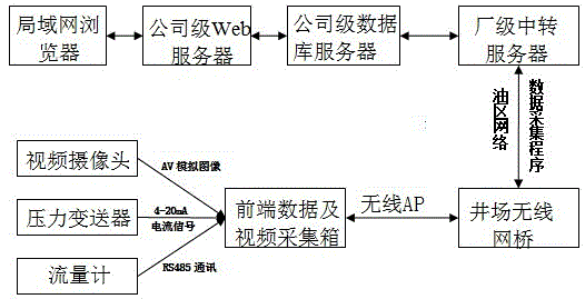
[0024] In order to solve the problem that the existing technology cannot realize remote monitoring of the current water plugging and profile control construction in the oilfield, and the on-site construction data cannot be analyzed in real time. This embodiment provides a mobile oilfield water plugging and profile control remote monitoring system based on Web technology, including front-end data and video acquisition boxes, measuring equipment connected to the front-end data and video acquisition boxes through cables, video cameras, and network equipment. and Web publishing system;
[0025] Among them, measuring equipment is used to provide and send construction data under water plugging and profile control;
[0026] The video camera is used to convert the on-site image of water plugging and profile control into electrical signals;
[0027] Front-end data and video acquisition box, including network video server DVS 8, remote measurement and control terminal remote measuremen...
Embodiment 2
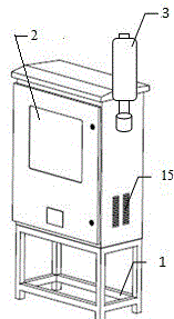
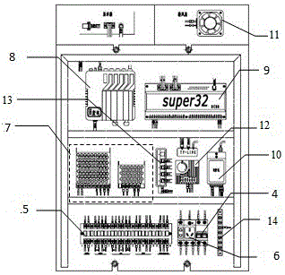
[0032] Such as figure 1 , 2 As shown, the front-end data and video acquisition box consists of box bracket 1, heat dissipation vent 15, integrated touch LCD screen 2, wireless AP 3, air switch 4, cable terminal 5, three-hole socket 6, switching power supply 7, Network video server DVS 8, remote measurement and control terminal remote measurement and control terminal RTU 9, GPR module, heat dissipation electric fan 11, heat dissipation fan temperature controller 12, network router 13, and ground wire terminal 14. The switching power supply 7 is responsible for supplying power to the network video server DVS 8 and the remote measurement and control terminal RTU. The cooling fan temperature controller 12 is responsible for controlling the cooling fan switch at the set temperature to ensure that the equipment in the box is within a reasonable operating temperature range. The network router passes the network cable It is connected with the remote measurement and control terminal R...
Embodiment 3
[0038] In order to apply the present invention in areas that cannot be covered by the oil network, this embodiment is in the GPRS transmission mode, such as Figure 4 As shown, the front-end data and video acquisition box data acquisition and transmission system in GPRS mode: the flowmeter, pressure transmitter and video camera are connected to the front-end data and video acquisition box through cable terminal 5, and the cable terminal 5 is connected to the network The video server DVS 8 is connected with the remote measurement and control terminal RTU.
[0039] The real-time injection flow data and real-time injection pressure data obtained by the flowmeter and pressure transmitter are sent to the remote measurement and control terminal RTU through the cable terminal 5, and the network video server DVS 8 collects the video obtained by the video camera 3, and compresses and encodes it, and then Send the video directly to the company-level database server directly through the ...
PUM
 Abstract
Description
Claims
Application Information
 - R&D
- Intellectual Property
- Life Sciences
- Materials
- Tech Scout
- Unparalleled Data Quality
- Higher Quality Content
- 60% Fewer Hallucinations
Browse by: Latest US Patents, China's latest patents, Technical Efficacy Thesaurus, Application Domain, Technology Topic, Popular Technical Reports.
© 2025 PatSnap. All rights reserved.Legal|Privacy policy|Modern Slavery Act Transparency Statement|Sitemap|About US| Contact US: help@patsnap.com


