Cooling element for a melting furnace

A technology for cooling elements and furnaces, which is applied in the direction of furnace cooling devices, furnace cooling, furnace components, etc., can solve problems such as heat transfer effects, and achieve the effects of optimized manufacturing methods, durable welds, and reliable processes

Active Publication Date: 2015-05-06
KME特殊产品和解决方案有限公司
View PDF7 Cites 2 Cited by
  • Summary
  • Abstract
  • Description
  • Claims
  • Application Information

AI Technical Summary

Problems solved by technology

[0010] But the example of the cooling box described in DE4035894C1 also has a disadvantage, because the explosive joining of the metal cover plate with the cooling tube does not take place and the heat transfer is thus affected

Method used


Image

  • Cooling element for a melting furnace
  • Cooling element for a melting furnace
  • Cooling element for a melting furnace

Examples


Embodiment Construction

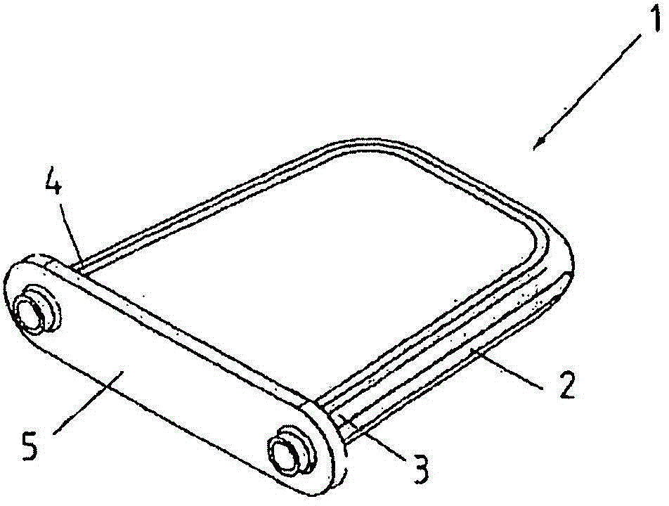
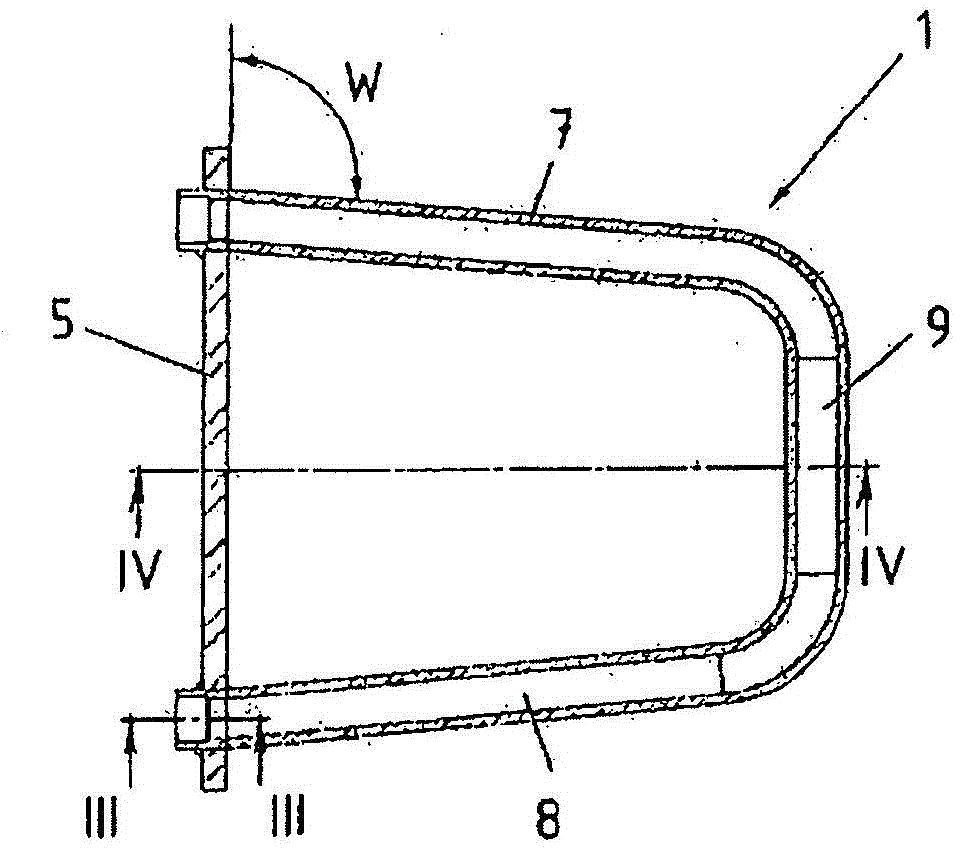
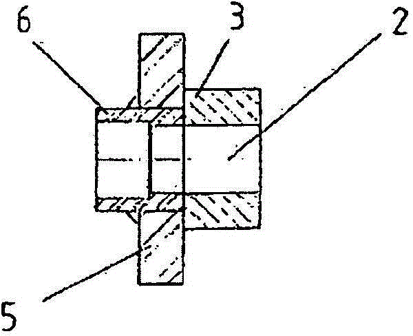
[0045] figure 1 A cooling element 1 is shown for installation into the wall of a furnace. The cooling element 1 comprises a U-shaped curved cooling tube 2 which, in a manner not shown, passes through the furnace shell and protrudes into the furnace interior. The cooling tube 2 has two ends 3 , 4 which are connected to a common plate-shaped support element 5 . Depend on figure 2 and 3 It can be seen that the cooling tube 2 does not pass through the carrier element 5 with its end 3 , but is only fastened to the opening of the carrier element 5 . A socket 6 is fastened to this opening of the carrier element 5 by welding. The connection piece 6 is used for coupling with other pipe sections in a manner not described.

[0046] In the exemplary embodiment, the connecting piece 6 is made of steel, while the cooling pipe 2 is made of copper material. Firstly, the connecting pipe 6 is connected with the cooling pipe by welding. This can preferably be achieved by friction welding...


PUM


Abstract

The invention relates to a cooling element for a melting furnace, having at least one cooling pipe for passing through a coolant, and having a support element (21) to which the at least one cooling pipe (2, 20) is fastened, wherein at least one cover plate (22, 23) is welded to the at least one cooling pipe (2, 20), wherein the at least one cooling pipe (2, 20) has at least one bead (14, 15) which extends in the longitudinal direction of the at least one cooling pipe (2, 20) and to which the at least one cover plate (22, 23) is welded.

Description

technical field [0001] The invention relates to a cooling element for a furnace according to the features of the preamble of claim 1 . Background technique [0002] Furnaces typically include vessels made of steel. In order to protect the steel container, a water cooling element is fixed inside the wall of the container. The intermediate space between the water cooling elements is filled with refractory material, such as prefabricated bricks or cast material. The surface in front of the cooling element is also shielded in this way. [0003] Water-cooled cooling elements of the prior art are roughly divided into two types, one of which has planar cooling devices which cover substantially the entire inside of the furnace. These cooling elements are generally made of copper and have a hot-forged structure, which is drilled deep for the conduction of the cooling water. Elements made of gray cast iron comprising cast-in tubes are also known. Cooling elements of this construc...

Claims


Application Information

Patent Timeline
Patent Type & Authority Applications(China)
IPC IPC(8): C21B7/10F27B1/24F28F3/12F27D1/12F27D9/00
CPCF27D1/12B23P15/26C21B7/10F27B1/24F27D9/00F27D2009/0029F27D2009/0048F27D2009/0062F28F3/12Y10T29/49359
Inventor C·德拉特纳
Owner KME特殊产品和解决方案有限公司
Why Eureka
Try Eureka