Hydraulic control system

A technology of hydraulic control system and controller, which is applied in fluid pressure actuation system components, fluid pressure actuation devices, accumulator devices, etc., and can solve problems such as difficulty in adaptation and difficulty in carrying large accumulators

Inactive Publication Date: 2015-05-06
CATERPILLAR INC
View PDF5 Cites 4 Cited by
  • Summary
  • Abstract
  • Description
  • Claims
  • Application Information

AI Technical Summary

Problems solved by technology

Such a large accumulator may be difficult to carry on the machine due to space constraints
Additionally, such systems ma

Method used


Image

  • Hydraulic control system
  • Hydraulic control system
  • Hydraulic control system

Examples


Embodiment Construction

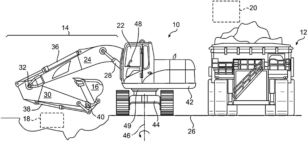
[0012] figure 1 An exemplary machine 10 is shown having a number of systems and components that cooperate to excavate and load material onto nearby transport vehicles 12 . In one example, machine 10 may embody a hydraulic excavator. It is contemplated, however, that machine 10 may embody another swing-type excavation or material handling machine, such as a backhoe, face shovel, dragline, or other similar machine. Among other things, machine 10 may include an implement system 14 configured to move implement 16 between a digging position 18 in a ditch or at a pile of ground and a dumping position 20 (eg, on top of transport vehicle 12 ). In addition, machine 10 may include an operator station 22 for manually controlling implement system 14 . It is contemplated that machine 10 may perform operations other than truck loading, such as lifting, trenching, and material handling, if desired.

[0013] Implement system 14 may include linkage structures actuated by fluid brakes to mov...


PUM


Abstract

A hydraulic control system includes an implement movable to perform an excavation cycle having a plurality of segments, a variable displacement motor configured to swing the implement at a desired speed during the excavation cycle, and a pump configured to pressurize fluid directed to drive the motor. The system further includes an accumulator configured to selectively receive fluid discharged from the motor via a charge valve, and to discharge fluid to the motor via a discharge valve. The system includes a selector valve fluidly connected to the charge valve and the discharge valve. The system also includes a controller configured to vary displacement of the motor, resulting in the desired speed.

Description

technical field [0001] The present invention generally relates to a hydraulic control system, in particular to a hydraulic control system capable of realizing energy recovery of a swing motor. Background technique [0002] Swing excavators, such as hydraulic excavators and front buckets, require a lot of hydraulic pressure and flow to move material from the digging position to the dumping position. These machines direct high pressure fluid from an engine driven pump through a swing motor to accelerate the loaded implement at the beginning of each swing, and then restrict fluid flow out of the motor at the end of each swing to slow and stop the implement. [0003] One problem associated with this type of hydraulic device involves efficiency. In particular, at the end of each swing, the fluid exiting the swing motor is at a relatively high pressure due to the deceleration of the loaded implement. Unless recovered, the energy associated with high pressure fluids can be wasted...

Claims


Application Information

Patent Timeline
IPC IPC(8): E02F9/22F15B13/02
CPCE02F9/2217E02F9/123E02F9/2296F15B1/024F15B21/14F15B2211/20546F15B2211/212F15B2211/6306F15B2211/6313F15B2211/6336F15B2211/665F15B2211/6652F15B2211/6658F15B2211/7058F15B2211/75F15B2211/763F15B2211/88
Inventor 马鹏飞R·N·彼得森J·张D·陈尚同林
Owner CATERPILLAR INC
Why Eureka
Try Eureka