Injection type rotational flow continuous separator

A separator and ejector technology, which is used in cyclone devices, centrifugal separation water/sewage treatment, and devices whose axial directions of cyclone can be reversed. large problems, to achieve the effects of good mobility, broadening the application base, and short separation time

Inactive Publication Date: 2015-05-13
HARBIN INST OF TECH
View PDF6 Cites 3 Cited by
  • Summary
  • Abstract
  • Description
  • Claims
  • Application Information

AI Technical Summary

Problems solved by technology

[0008] The present invention solves the problems that the existing cyclone continuous separator adopts backflow sewage to eject the dirt and sundries, which has the problems of lar

Method used


Image

  • Injection type rotational flow continuous separator
  • Injection type rotational flow continuous separator

Examples


specific Embodiment approach 1

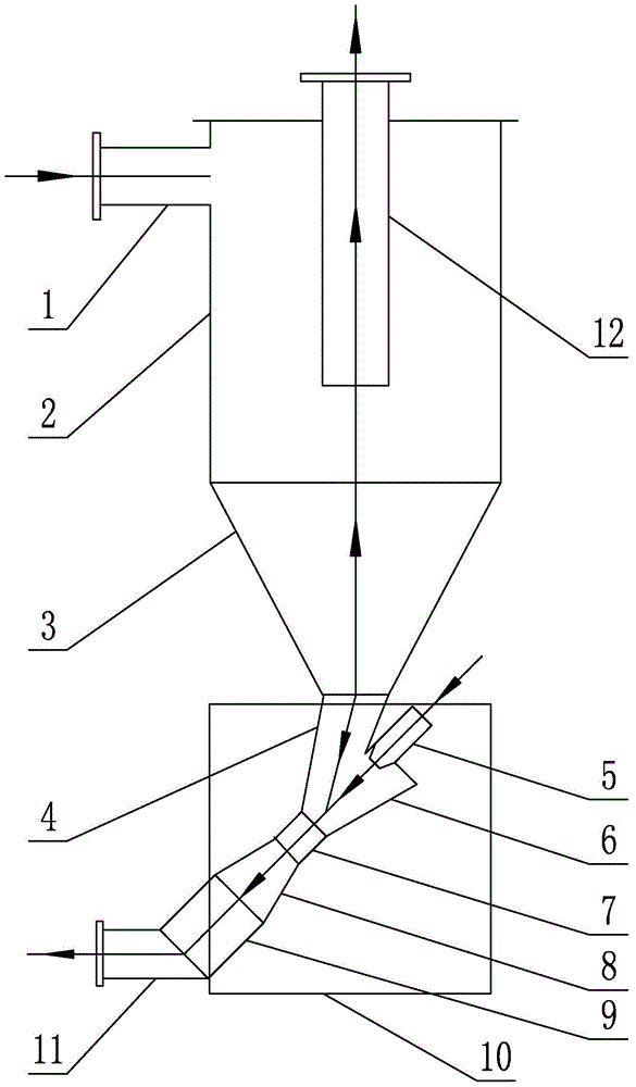
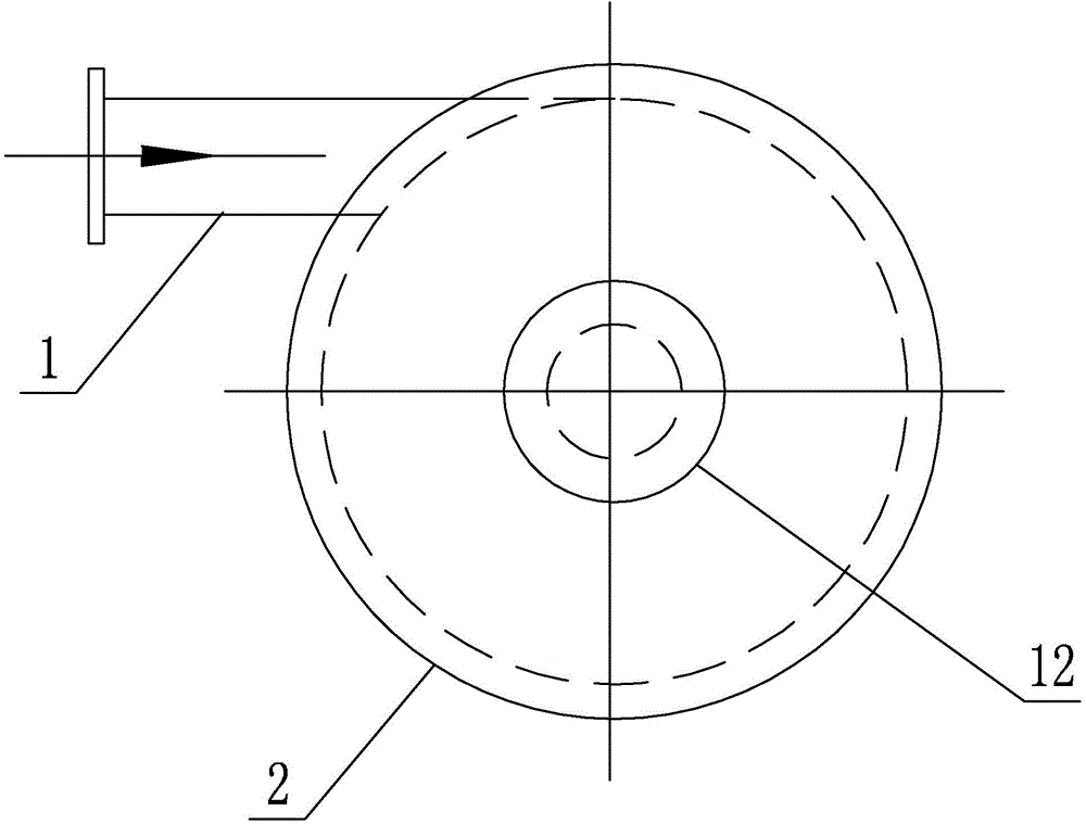
[0019] Specific implementation mode one: as Figure 1~2 As shown, the injection type cyclone continuous separator of the present embodiment comprises a sewage inlet pipe 1, a cylinder 2, a conical cylinder 3, a sewage outlet pipe 11 and an overflow pipe 12, and the outer diameter of the large end of the conical cylinder 3 is the same as that of the cylinder. The outer diameters of 2 are set equal, the lower end of the cylinder 2 communicates with the large end of the conical cylinder 3, the sewage inlet pipe 1 is arranged tangentially on the outer wall of the cylinder 2, and the sewage inlet pipe 1 communicates with the upper part of the cylinder 2, The overflow pipe 12 is vertically arranged on the axis of the cylinder 2; the separator also includes an ejector return device 10, which includes a blowdown pipe 4, a nozzle 5, a mixing chamber 6, a throat 7, a diffuser Pipe 8 and water mixing outlet pipe 9, mixing chamber 6, throat 7, diffuser pipe 8 and water mixing outlet pipe ...

specific Embodiment approach 2

[0020] Specific implementation mode two: as figure 1 As shown, the nozzle 5 and the mixing chamber 6 are arranged coaxially in this embodiment. Such a design makes it easy for the liquid sprayed from the nozzle 5 to smoothly inject the sewage containing more dirt and debris discharged from the sewage pipe 4 into the throat 7, so as to avoid dead ends and blockage of sewage discharge, and at the same time, it also helps to reduce sewage passing through the throat 7. part of the energy consumption. Other components and connections are the same as those in the first embodiment.

specific Embodiment approach 3

[0021] Specific implementation mode three: as figure 1 As shown, the cylinder 2 and the conical cylinder 3 are integrally made in this embodiment.

[0022] With such a design, the manufacturing cost is low, and at the same time, the stability of the cyclone continuous separator can be increased. Other compositions and connections are the same as those in Embodiment 1 or 2.

[0023] Specific implementation mode four: as figure 1 As shown, the angle formed between the axis of the sewage outlet pipe 11 and the axis of the mixed water outlet pipe 9 in this embodiment is 110-160°. Such design is to facilitate the outflow of sewage and dirt and avoid blockage caused by straight elbows or near-straight elbows. Other components and connections are the same as those in the third embodiment.


PUM


Abstract

The invention discloses an injection type rotational flow continuous separator, relates to a rotational flow continuous separator and solves the problems that an existing rotational flow continuous separator adopts reflux waste water to inject dirty sundries, so that the water consumption is large, water cannot be taken on the spot, a pipeline is overlong, and the consumption of pipe materials is too high. The lower end of a cylinder is mutually communicated with the large end of a cone barrel, a waste water inlet pipe is tangentially arranged on the outer side wall of the cylinder, the waste water inlet pipe is communicated with the upper part of the cylinder, and an overflow pipe is vertically arranged on the axis of the cylinder; a mixing chamber, a throat part, a diffuser pipe and a mixed water outlet pipe are successively arranged in the direction of the axis in an inclined manner from top to bottom, and the mixing chamber, the throat part, the diffuser pipe and the mixed water outlet pipe are successively communicated; the lower end of the cone barrel is communicated with the mixing chamber through a blowdown pipe, a spray nozzle is arranged at the upper end of the mixing chamber, the inner diameter of the mixing chamber is arranged in an gradual constriction manner from top to bottom, the inner diameter of the diffuser pipe is arranged in an gradual extension manner from top to bottom, and a waste water outlet pipe is communicated with the lower end of the mixed water outlet pipe. The injection type rotational flow continuous separator disclosed by the invention is used for treating urban original waste water.

Description

technical field [0001] The invention relates to an ejector type cyclone continuous separator, which belongs to the technical field of sewage treatment. Background technique [0002] At present, the sewage anti-blocking machine includes a rotary elliptical tube sewage filter, a hydraulic continuous self-cleaning sewage anti-blocking machine, a rotating plate type automatic decontamination water intake device, a rotating cylinder type automatic decontamination water intake device, an open cycle integrated sewage water intake device, built-in Sewage shell and tube heat exchangers of spring cleaners, self-cleaning sewage heat exchangers, etc. [0003] The rotary oval tube sewage filter is driven by the motor to rotate, the sewage enters the cavity and is filtered by the orifice plate, and the dirt on the orifice plate is removed by the sewage hole under the action of the rotary oval tube. In the actual operation process, there is a certain gap between the rotating oval tube and...

Claims


Application Information

Patent Timeline
IPC IPC(8): B04C5/00B04C5/08B04C5/12C02F1/38
Inventor 倪龙姚杨田金乙赵加宁
Owner HARBIN INST OF TECH
Why Eureka
Try Eureka