Automatic expanding feeder for radiating tube

A heat pipe and feeder technology, applied in heat exchange equipment, push-out equipment, etc., can solve the problems of high cost, unable to keep up with the production speed of fins, etc., and achieve the effect of automatic completion, reasonable layout design, and convenient use.

Active Publication Date: 2015-05-13
NINGBO RONGZHI AUTOMATION TECH
View PDF6 Cites 4 Cited by
  • Summary
  • Abstract
  • Description
  • Claims
  • Application Information

AI Technical Summary

Problems solved by technology

[0004] Due to the company's multiple fin forming and automatic cutting patented technologies, the production speed of fins has been greatly improved. In the past, the speed of manual expansion of heat pipes has been unable to keep up with the production speed of fins, and the cost is high.

Method used


Image

  • Automatic expanding feeder for radiating tube
  • Automatic expanding feeder for radiating tube
  • Automatic expanding feeder for radiating tube

Examples


Embodiment Construction

[0021] The present invention will be further described in detail below in conjunction with the accompanying drawings and embodiments.

[0022] Such as Figure 1~4 Shown is a preferred embodiment of the present invention.

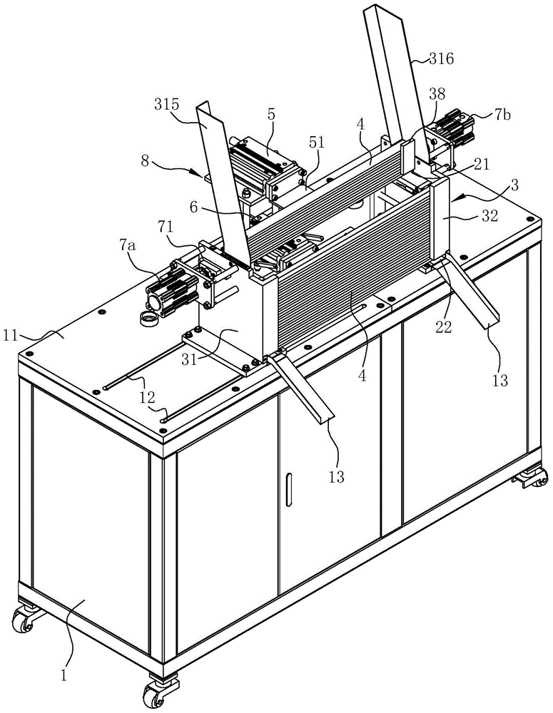
[0023] A cooling pipe automatic flare feeding machine, comprising a frame 1, the upper part of the frame 1 has a mounting platform 11, the bottom of the frame is provided with rollers, and the mounting platform 11 of the frame 1 is provided with a stacking part, a feeding part and an expanding part. mouth part.

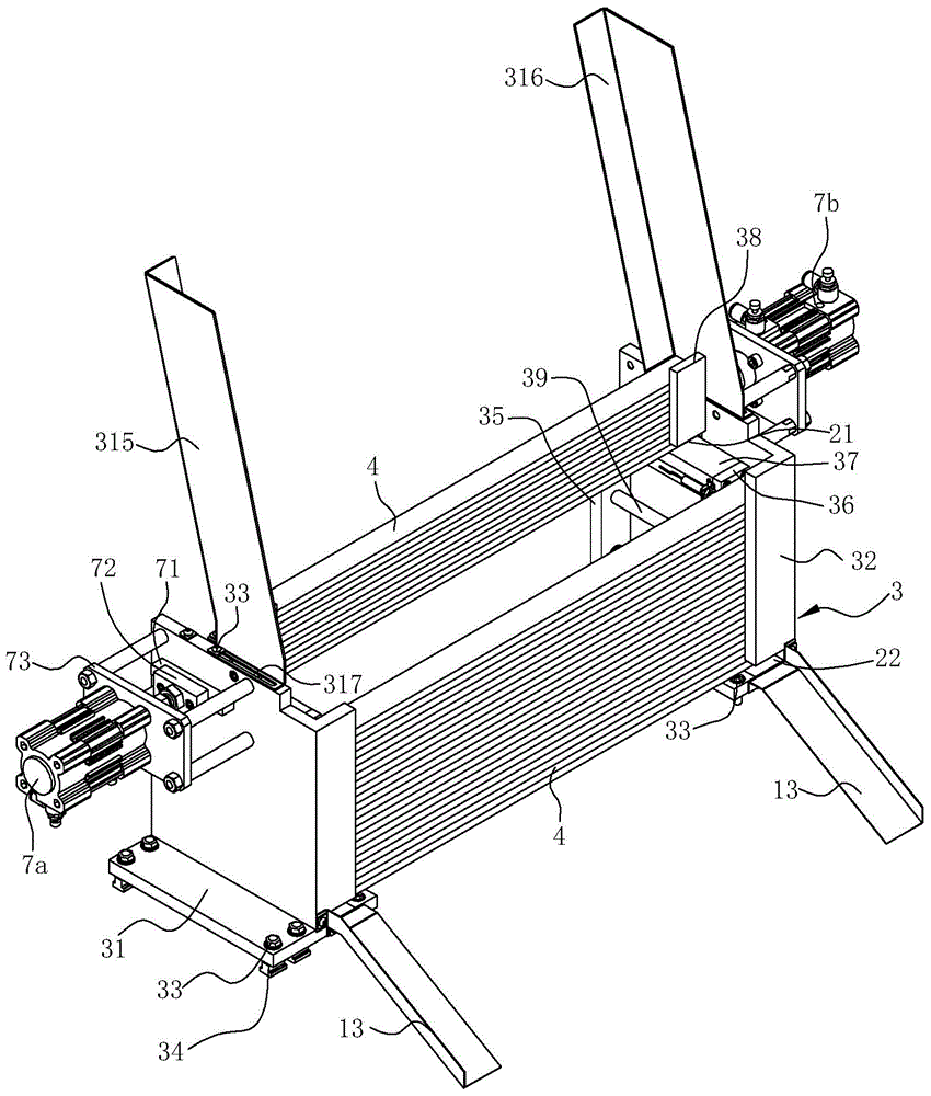
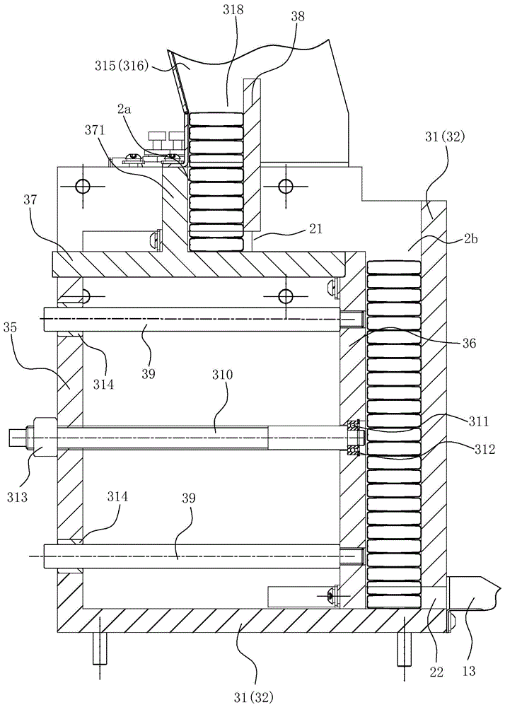
[0024] Such as figure 2 , 3 As shown, the stacking part includes a stacker 3, which has an upper stocking tank 2a vertically arranged for stacking heat pipes 4 to be flared, and vertically arranged for stacking the heat dissipation pipes 4 after flared. The lower storage tank 2b of the pipe 4, the lower storage tank 2b is located at the front and lower part of the upper storage tank 2a, a position sensor is installed on the top of the lower sto...


PUM


Abstract

The invention relates to an automatic expanding feeder for a radiating tube. The automatic expanding feeder is characterized by comprising a rack, a stacking part, a feeding part and an expanding part, wherein the stacking part comprises a stacking frame, the stacking frame is provided with an upper stacking groove and a lower stacking groove, a feeding port is arranged at the lowest end of the front of the upper stacking groove, and a discharging port is arranged at the lowest end of the front of the lower stacking groove; the feeding part comprises a feeding push plate driven by a feeding air cylinder and a discharging push plate driven by a discharging air cylinder; the expanding part comprises a left expanding air cylinder and a right expanding air cylinder, the left expanding air cylinder and the right expanding air cylinder are arranged on the left and the right of the stacking frame respectively, an air cylinder rod of the left expanding air cylinder and an air cylinder rod of the right expanding air cylinder are each fixedly provided with an expanding punch, and the expanding punches penetrate through the left sidewall and the right sidewall of the stacking frame respectively and correspond to openings in the two ends of the radiating tube located at the lowest end of the upper stacking groove. The feeder can automatically complete the expanding process for the radiating tube and convey the radiating tube to the next station after the radiating tube is expanded.

Description

technical field [0001] The invention relates to a processing equipment for a plate-fin heat dissipation pipe, in particular to a heat dissipation pipe automatic flare feeding machine for realizing automatic heat dissipation pipe flare. Background technique [0002] Plate-fin heat exchangers are heat exchangers for various types of gas separation equipment. They are widely used in the fields of automobiles, petrochemicals, and aerospace. Plate-fin heat exchangers have the advantages of compact structure, light weight, and high heat exchange efficiency. The heat exchange efficiency is 30% higher than other heat exchangers, and the heat pipe is an important part of the radiator. [0003] In the production process of the automobile heat exchanger, there is a process of inserting the fins into the heat dissipation pipes. In order to make the fins penetrate into the heat dissipation pipes smoothly, the heat dissipation ports need to be flared. Existing flaring The methods are all...

Claims


Application Information

Patent Timeline
Patent Type & Authority Applications(China)
IPC IPC(8): B21D41/02B21D45/02
CPCB21D41/02B21D45/02B21D53/06
Inventor 王荣董明智倪泉斌毛国平
Owner NINGBO RONGZHI AUTOMATION TECH
Why Eureka
Try Eureka