Multifunctional CNC spring forming machine

A forming machine and multi-functional technology, which is applied in the direction of manufacturing springs from wires, other household appliances, household appliances, etc., can solve the problems of inaccurate wire feeding position, insufficient clamping force of metal wire, and great influence on the production efficiency of spring machines, etc.

Active Publication Date: 2015-05-13
SUZHOU ZHONGTAI POWER SPRING
View PDF9 Cites 1 Cited by
  • Summary
  • Abstract
  • Description
  • Claims
  • Application Information

AI Technical Summary

Problems solved by technology

[0002] In metal wire processing, it is often necessary to use a spring forming machine to bend wires of different diameters at different angles and in different directions. Usually, a spring forming machine is mainly composed of a wire feeding transfer mechanism, a straightening mechanism, a crimping mechanism and a cutting mechanism. and other parts, for example, the invention patent of Chinese Patent Publication No. CN104084509A discloses such a spring forming machine, wherein the wire feeding and rotating wire transmission mechanism usually includes a winding reel and a wire feeding device, and the metal wire required for spring forming Wound on the winding reel, the wire feeding device clamps and pushes the metal wire to the crimping position, the straightening mechanism performs pre-alignment on the metal wire, the crimping forming mechanism curls and forms the steel wire fed by the wire feeding mechanism, and the cutting mechanism It is used to cut the preliminarily formed spring from the steel wire; however, the spring forming machine in the prior art has the problems of insufficient clamping force on the wire and inaccurate wire feeding position in the wire feeding device, which affects the post-processing The accuracy of the spring has a great influence on the production efficiency of the spring machine

Method used


Image

  • Multifunctional CNC spring forming machine
  • Multifunctional CNC spring forming machine
  • Multifunctional CNC spring forming machine

Examples


Embodiment Construction

[0018] The specific implementation manners of the present invention will be further described in detail below in conjunction with the accompanying drawings and embodiments. The following examples are used to illustrate the present invention, but are not intended to limit the scope of the present invention.

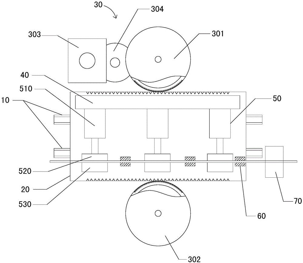
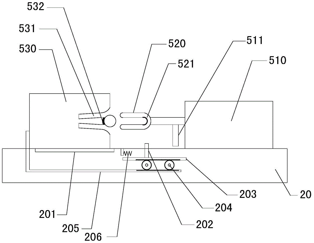
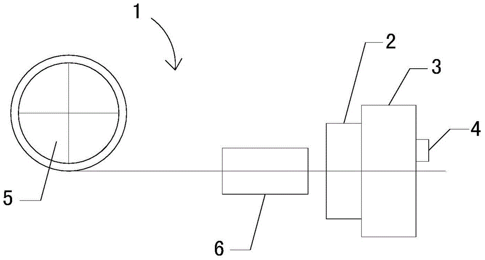
[0019] see Figure 1 to Figure 3 , a multi-functional computer spring forming machine according to a preferred embodiment of the present invention includes a wire feeding and turning transmission mechanism 1, a straightening mechanism 2, a crimping forming mechanism 3 and a cutting mechanism 4, and the wire feeding and turning transmission mechanism 1 includes winding The wire reel 5 and the wire feeding device 6, the metal wire passes through the wire feeding and turning transmission mechanism 1, the straightening mechanism 2, the crimp forming mechanism 3 and the cutting mechanism 4 in turn, and finally is formed in the crimp forming mechanism and is cut by the cutting m...


PUM


Abstract

The invention relates to spring forming devices, in particular to a multifunctional CNC spring forming machine. The multifunctional CNC spring forming machine comprises a wire feeding and transferring drive mechanism, a straightening mechanism, a curl forming mechanism and a cut-off mechanism. The wire feeding and transferring drive mechanism comprises a wire spool and a wire feeding device. The wire feeding device comprises guide rails, a sliding table, a power unit, a fixed base, clamping units, wire supporting tables and a wire guide table. The power unit controls the sliding table to slide relatively on the guide rails, and the fixed base is fixed on the sliding table. The number of the clamping units is at least three, the ends of the clamping units are fixed on the fixed base in parallel, and the wire supporting tables are respectively arranged between the clamping units. The wire guide table is arranged between the wire feeding device and the straightening mechanism. Each clamping unit comprises a hydraulic oil cylinder, a chuck and a clamping base, wherein the chuck is arranged at the output end of the hydraulic oil cylinder, and the clamping base is arranged on the other side, opposite to the chuck, of the sliding table and is matched with the chuck. The multifunctional CNC spring forming machine is high in clamping force to metal wires and accurate in wire feeding position.

Description

technical field [0001] The invention relates to a spring forming device, in particular to a multifunctional computer spring forming machine. Background technique [0002] In metal wire processing, it is often necessary to use a spring forming machine to bend wires of different diameters at different angles and in different directions. Usually, a spring forming machine is mainly composed of a wire feeding transfer mechanism, a straightening mechanism, a crimping mechanism and a cutting mechanism. and other parts, for example, the invention patent of Chinese Patent Publication No. CN104084509A discloses such a spring forming machine, wherein the wire feeding and rotating wire transmission mechanism usually includes a winding reel and a wire feeding device, and the metal wire required for spring forming Wound on the winding reel, the wire feeding device clamps and pushes the metal wire to the crimping position, the straightening mechanism performs pre-alignment on the metal wir...

Claims


Application Information

Patent Timeline
IPC IPC(8): B21F35/00B21F23/00
Inventor 顾志卓
Owner SUZHOU ZHONGTAI POWER SPRING
Why Eureka
Try Eureka