

Robot, control device, robot system and robot control method
A robot system and control device technology, applied in control/adjustment systems, robots, program-controlled manipulators, etc., can solve problems such as broken parts, inability to fasten screws, and undisclosed pressing parts.
- Summary
- Abstract
- Description
- Claims
- Application Information
AI Technical Summary
Problems solved by technology
Method used
Image

Examples
no. 2 approach >
[0188] Hereinafter, a second embodiment will be described. In addition, the same code|symbol is used for the same part as 1st Embodiment, and description is abbreviate|omitted.
[0189] Figure 13 It is a figure explaining the 1st work example performed by a robot. In the first work example, the snap ring A200 is fitted (assembled) into the rod-shaped shaft portion A150 of the workpiece A100.
[0190] The workpiece A100 has a rectangular parallelepiped main body A110 and a rod-shaped shaft A150 substantially perpendicular to one surface of the main body A110. A groove (not shown) into which the snap ring A200 fits is formed on the outer periphery (side surface) of the shaft portion A150.
[0191] The retaining ring A200 has a ring shape when viewed from the Z direction, and a part of the ring is cut out. The snap ring A200 is fitted into a groove (not shown) formed on the outer periphery of the shaft A150 from a direction substantially perpendicular to the longitudinal dir...
no. 3 approach >
[0240] Hereinafter, a third embodiment will be described. In addition, the same code|symbol is used for the same part as 1st Embodiment and 2nd Embodiment, and description is abbreviate|omitted.
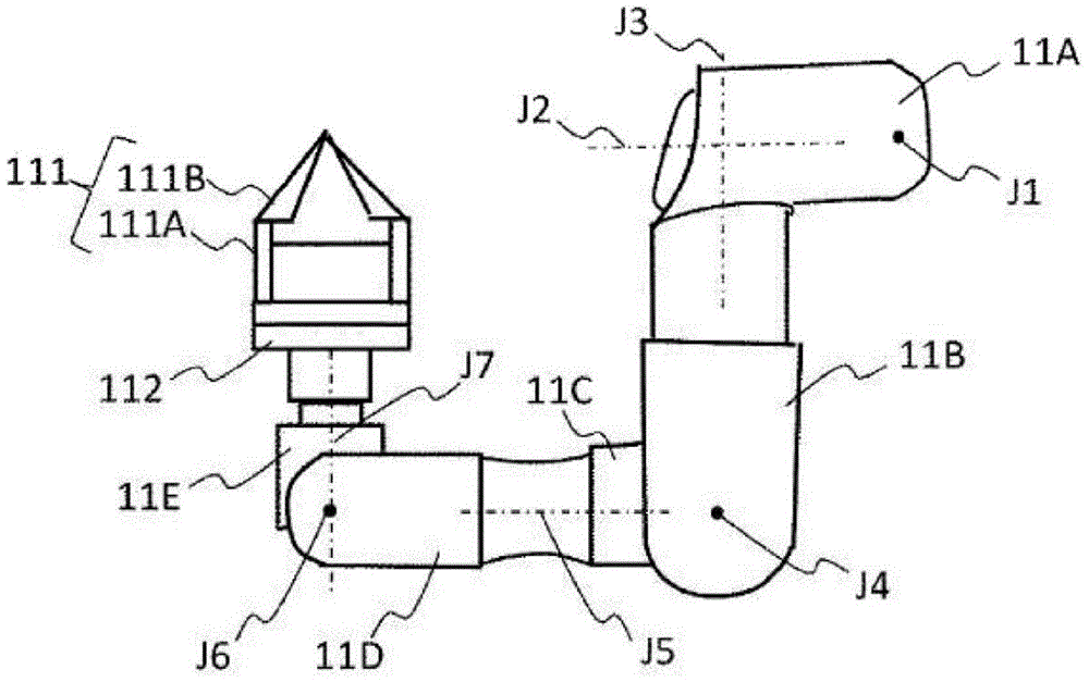
[0241] Figure 23A , Figure 23B It is a perspective view showing details of the hand 111 . Figure 23A It is the figure which made the gripping surface 111B-1 (details mentioned later) of the finger 111B contact each other, Figure 23B It is the figure which separated the grip surface 111B-1.
[0242] The hand 111 includes a main body 111A, fingers 111B, a bottom plate 111C, a movable part 111D, and a transmission shaft 111E. The external shape of the main body part 111A is substantially rectangular parallelepiped, and the movable part 111D is arrange|positioned around it. The finger 111B is provided on the movable part 111D. The tip of the finger 111B is formed substantially in the shape of a quadrangular pyramid, and at least one of the side surfaces of the quadrangular pyra...
no. 4 approach >
[0344] Hereinafter, a fourth embodiment will be described. In addition, the same code|symbol is attached|subjected to the same part as 1st Embodiment - 3rd Embodiment, and description is abbreviate|omitted.
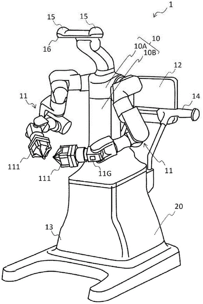
[0345] Figure 37 It is a diagram showing a schematic configuration example of a robot system 1000 according to an embodiment of the present invention.
[0346] The robot system 1000 of this embodiment includes a robot 10000 , a control device 20000 , and an imaging unit 30000 . The robot 10000 includes a control device 20000 therein. The imaging unit 30000 and the control device 20000 of the robot 10000 are connected via a line 40000 so as to be communicable. In this embodiment, the line 40000 is wired, but it may be wireless.
[0347] The robot system 1000 is a system that works on a tool held by a robot. In this embodiment, tools are manufactured for human use, for example. Specifically, the tools are, for example, an E-ring setter for inserting the E-ring, and a...
PUM
 Abstract
Description
Claims
Application Information