
Rotor end surface temperature measuring device of traction molecular pump

A technology for temperature measuring devices and molecular pumps, which is applied to measuring devices, components of pumping devices for elastic fluids, non-volume pumps, etc., and can solve the problems of rotor deformation, processing difficulty of molecular pump assembly parts and increased assembly difficulty , It is impossible to install temperature measuring devices at will, etc., to achieve the effect of simplifying the structure and ensuring the flow area

Active Publication Date: 2017-02-22
RES INST OF PHYSICAL & CHEM ENG OF NUCLEAR IND
View PDF7 Cites 0 Cited by
  • Summary
  • Abstract
  • Description
  • Claims
  • Application Information

AI Technical Summary

Problems solved by technology

When the rotor rotates at a high speed, especially an ultra-high speed, the rotor itself will be deformed, and it is very difficult to measure the temperature of its end surface in real time, and the structure of the molecular pump itself is relatively compact and it is impossible to install a temperature measuring device at will. Therefore, how to Accurate and real-time measurement of the surface temperature without affecting the performance of the molecular pump is a difficult problem in this field at this stage
If the existing temperature measuring device is used and installed on the molecular pump assembly with an annular disc type molecular pump, not only the processing difficulty and assembly difficulty of the entire molecular pump assembly will be greatly increased, but also it cannot be guaranteed that the Replace the temperature measuring device at will without changing the performance

Method used


Image

  • Rotor end surface temperature measuring device of traction molecular pump
  • Rotor end surface temperature measuring device of traction molecular pump
  • Rotor end surface temperature measuring device of traction molecular pump

Examples


Embodiment Construction

[0039] Below, the present invention is described in detail with reference to accompanying drawing and embodiment:

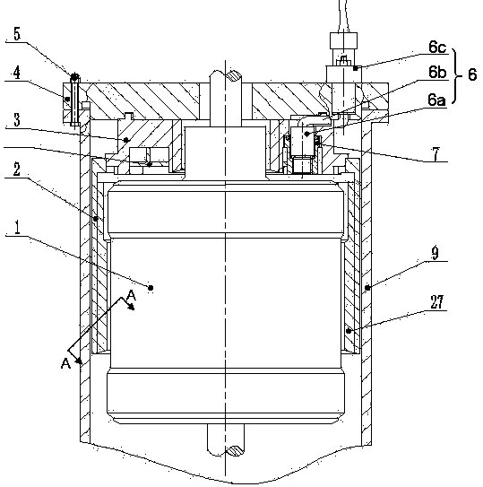
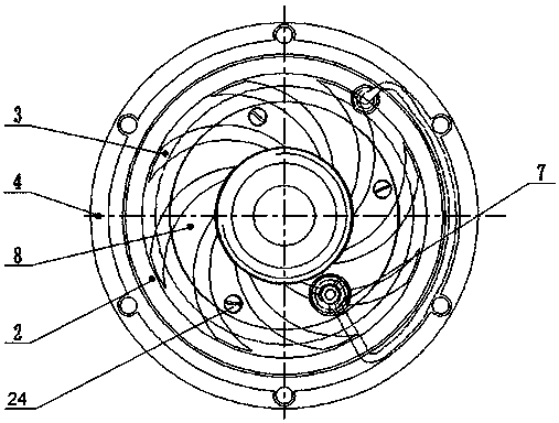
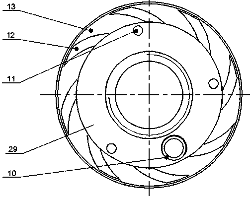
[0040] Such as Figure 1~12 As shown, a rotor end surface temperature measuring device of a traction molecular pump includes a cylindrical casing 9, a cylindrical rotor 1 is arranged inside the casing 9, and the end surface is fixed to the end surface flange 4 by bolts 5 inserted into the bolt holes 30, Inside the casing 9, on the periphery of the rotor 1, and coaxially with the rotor 1, a first-stage molecular pump 2 is arranged, and a third-stage molecular pump 3 is interference-connected with the first-stage molecular pump 2, and the second-stage molecular pump 8 is fixed on the second stage. In the three-stage molecular pump assembly groove 29, the inner wall of the cylindrical first-stage molecular pump 2 forms a helical first-stage pumping groove 27, and the lower end surface of the disc-shaped second-stage molecular pump 8 forms a plurality of evenly distr...


PUM


Abstract

The invention discloses a rotor end surface temperature measuring device for traction type molecular pumps. The rotor end surface temperature measuring device comprises an outer shell, a rotor, an end face flange, the first-stage molecular pump, the third-stage molecular pump and the second-stage molecular pump, wherein the third-stage molecular pump is in interference fit connection with the first-stage molecular pump; a screw is screwed into an end face flange threaded hole of the end face flange through a third-stage molecular pump connecting hole in the circumference of the third-stage molecular pump; the protruding end of the screw is located in a screw connecting hole in the circumference of the second-stage molecular pump; a transition part is fixed to the interior of an assembly threaded hole of an assembly stepped hole through external threads, and the free end of the transition part is located in a transition part insertion hole; an infrared probe in a temperature measurement assembly is screwed into an assembly screw hole of the transition part and is fixed to the third-stage molecular pump through the transition part. The temperature measurement assembly can be conveniently disassembled or assembled under the condition of guaranteeing the dynamic clearance of the second-stage molecular pump and the dynamic clearance of the third-stage molecular pump, and therefore the open area and pumping efficiency of a pumping tank are guaranteed.

Description

technical field [0001] The invention belongs to a temperature measuring device, in particular to a rotor end surface temperature measuring device of a traction molecular pump. Background technique [0002] The traction molecular pump relies on the gas molecules colliding with the high-speed rotor to gain momentum, thereby driving the gas molecules to the outlet of the pump. The change of the surface temperature of the rotor in the traction molecular pump can intuitively reflect the real-time working status and related performance of the device, so the real-time monitoring of the temperature is of great significance in the development of the device. When the rotor rotates at a high speed, especially an ultra-high speed, the rotor itself will be deformed, and it is very difficult to measure the temperature of its end surface in real time, and the structure of the molecular pump itself is relatively compact and it is impossible to install a temperature measuring device at will....

Claims


Application Information

Patent Timeline
Patent Type & Authority Patents(China)
IPC IPC(8): F04D19/04F04D29/64G01J5/00
CPCF04D19/042F04D27/001G01J5/0022F04D19/04F05D2270/804
Inventor 刘巍周勃韩莉果李德鑫
Owner RES INST OF PHYSICAL & CHEM ENG OF NUCLEAR IND
Learn More