Scanning synthetic aperture radar image quality improving method and device

A synthetic aperture radar, image quality technology, applied in measurement devices, radio wave measurement systems, radio wave reflection/re-radiation and other directions, can solve problems such as visual interference, increase computational burden, affect interpretation, etc. Improve, suppress or remove the effects of grating lobes, improve the effect of imaging algorithms

Active Publication Date: 2015-05-13
INST OF ELECTRONICS CHINESE ACAD OF SCI
View PDF4 Cites 4 Cited by
  • Summary
  • Abstract
  • Description
  • Claims
  • Application Information

AI Technical Summary

Problems solved by technology

[0003] At present, the processing methods for ScanSAR data mainly include SPEAN algorithm, improved SPEAN algorithm, extended CS algorithm, full-aperture imaging algorithm, etc. Among them, SPEAN algorithm and improved SPEAN algorithm are more commonly used when medium precision is required, but for high-precision requirements, the SPEAN algorithm and the improved SPEAN algorithm are not very effective, because these two algorithms only correct the linear range migration (RCM, range cell migration) part; the extended CS algorithm combines the advantages of the traditional CS and SPEAN algorithms, both Increased accuracy also improves efficiency, but this algorithm needs to process each burst of ScanSAR data separately, and then stitch them together in azimuth, which increases the computational burden; and, when a target consists of two different bursts There will be frequency discontinuity when splicing
[0004] Current full-aperture imaging algorithms, although processing preserves the phase information, produce results that have the same geometric properties as the corresponding strip images. However, in full-aperture imaging algorithms, successively processed bursts lead to unwanted generation in the shock response. Grating lobes seriously reduce the quality of ScanSAR images and affect interpretation
Although a low pass filter can mitigate the effect of grating lobes, the residual effect is enough to be visually disturbing, and there is currently no other way to address this

Method used


Image

  • Scanning synthetic aperture radar image quality improving method and device
  • Scanning synthetic aperture radar image quality improving method and device
  • Scanning synthetic aperture radar image quality improving method and device

Examples


Embodiment Construction

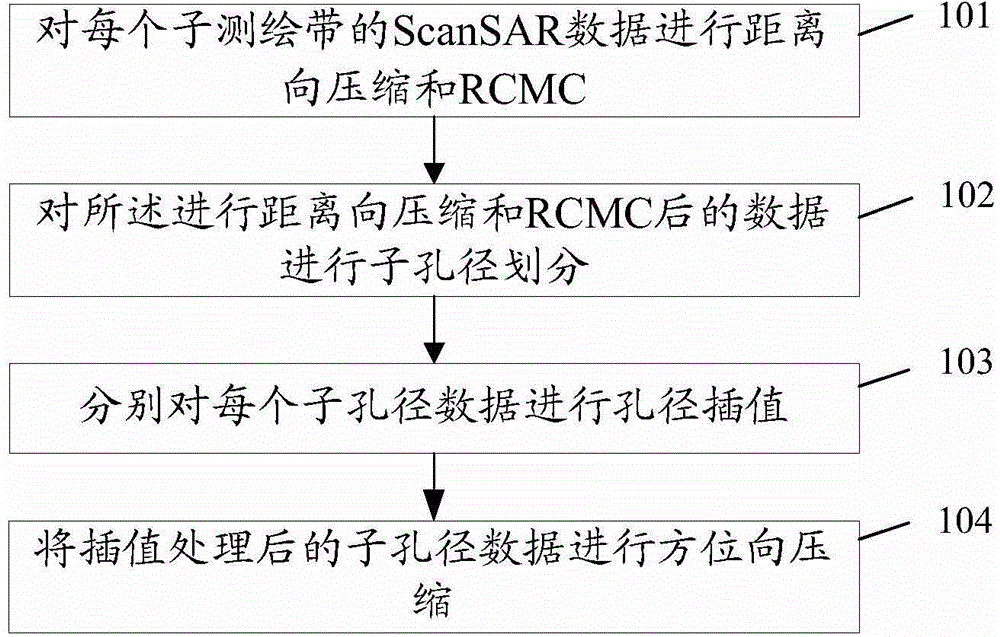
[0045] In the embodiment of the present invention, the ScanSAR data of each sub-swath is first subjected to range compression and RCMC; then the data after the range compression and RCMC is subjected to sub-aperture division; and then aperture interpolation is performed on each sub-aperture data respectively ; Finally, compress the interpolated sub-aperture data in azimuth direction to obtain the final ScanSAR image with improved quality.

[0046] In practical applications, a complete ScanSAR image includes multiple sub-swaths. The above process is for one sub-swath. For the ScanSAR data of each sub-swath, it needs to be processed according to the above process to complete the complete ScanSAR image. processing of data.

[0047] The implementation of the technical solutions of the embodiments of the present invention will be further described in detail below in conjunction with the accompanying drawings and specific embodiments.

[0048] figure 1 It is a schematic flow chart...


PUM


Abstract

The invention discloses a scanning synthetic aperture radar (ScanSAR) image quality improving method; the method comprises the following steps: applying range direction compression and range cell migration correction (RCMC) to ScanSAR data of each mapping sub-band; applying sub-aperture division to the data after being applied with the range direction compression and the RCMC; respectively applying aperture interpolation to each sub-aperture data; applying azimuth compression to the sub-aperture data after being applied with the interpolation. The invention further discloses a scanning synthetic aperture radar (ScanSAR) image quality improving device.

Description

technical field [0001] The present invention relates to the technical field of synthetic aperture radar (SAR, Synthetic Aperture Radar) data processing, in particular to a scanning synthetic aperture radar (Scanning Synthetic Aperture Radar, Scanning Synthetic Aperture Radar) image quality improvement method and device. Background technique [0002] ScanSAR is a SAR mode that obtains a wide swath by periodically switching the antenna beam angle from short-range to long-range. This mode can obtain a wider swath than traditional SAR systems. ScanSAR generally consists of several sub-swaths, and each sub-swath of ScanSAR data includes bursts separated by periodic data gaps. The so-called burst (burst) refers to a group of continuous pulse sequences from continuous transmission pulses. The azimuth resolution of the ScanSAR image is only determined by the duration of each burst, and each complete synthetic aperture length contains several bursts. [0003] At present, the proces...

Claims


Application Information

Patent Timeline
Patent Type & Authority Applications(China)
IPC IPC(8): G01S13/90G01S7/36
CPCG01S7/36G01S13/90G01S13/9011G01S13/9056
Inventor 李宁王宇邓云凯张志敏邢艳肖张毅赵凤军
Owner INST OF ELECTRONICS CHINESE ACAD OF SCI
Why Eureka
Try Eureka