Charging protection circuit used for capacitor voltage reduction

A capacitor voltage reduction and charging protection technology, applied in battery circuit devices, circuit devices, current collectors, etc., can solve the problems of damage to the battery, easy overcharge, no cost advantage, etc., to extend the service life, improve product performance, reduce The effect of material cost

Inactive Publication Date: 2015-05-13
怀化市红圳电子科技有限责任公司
View PDF8 Cites 6 Cited by
  • Summary
  • Abstract
  • Description
  • Claims
  • Application Information

AI Technical Summary

Problems solved by technology

[0004] 1) The overcharge-resistant rechargeable battery is highly polluting to the environment. When it is used without a charging protection circuit, it can only estimate the charging time, which is easy to overcharge and damage the battery. There is no full-fill prompt information, which is inconvenient to use
[0005] 2) The common battery charging protection circuit must add a high-power voltage stabilizing device. Compared with switching power supply step-down and transformer step-down circuits, there is no cost advantage

Method used


Image

  • Charging protection circuit used for capacitor voltage reduction
  • Charging protection circuit used for capacitor voltage reduction
  • Charging protection circuit used for capacitor voltage reduction

Examples


Embodiment 1

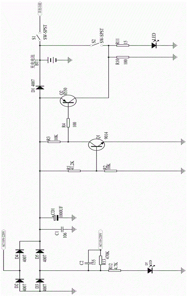
[0035] Such as figure 1As shown, the reverse switching element is a 4007 type rectifier diode D1; the battery overcharge detection circuit is composed of a 9014NPN type first transistor Q1, a first resistor R1, and a second resistor R2, and the battery over-full current The circuit is composed of an 8550PNP second transistor Q2, a third resistor R3 and a fourth resistor R4, wherein the first resistor R1 and the second resistor R2 are connected in series to form a voltage divider circuit between the output terminal of the rectifier circuit and the ground terminal Between, the base of the first transistor Q1 is connected to the connection point of the first resistor R1 and the second resistor R2, its emitter is grounded, one of its collectors is connected to the output terminal of the rectifier circuit through the third resistor R3, and the other is connected to the output terminal of the rectifier circuit through the fourth resistor R4 is connected to the base of the second tra...

Embodiment 2

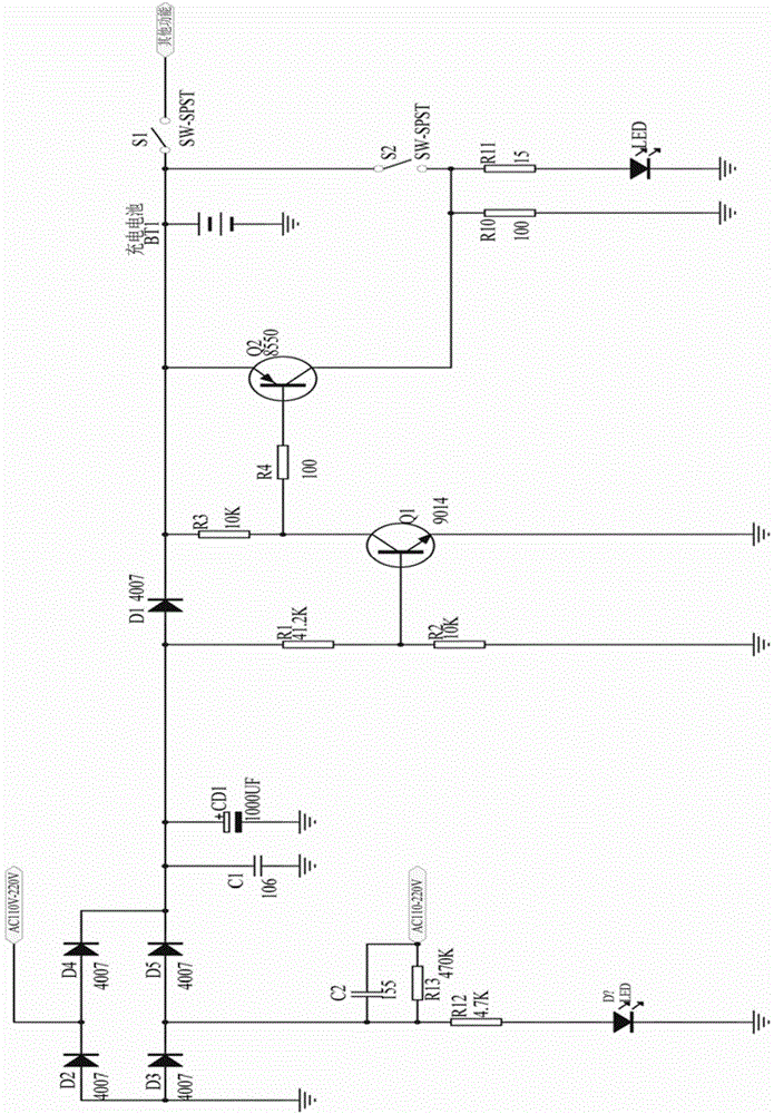
[0039] Such as figure 2 As shown, this embodiment is the same as the embodiment 1 except that the setting position of the rectifier diode D1 is different from that of the embodiment 1, which is a modification of the embodiment 1. Wherein, the positive terminal of the rectifying diode D1 is connected to the output terminal of the rectifying circuit, and the negative terminal thereof is connected to the emitter of the second transistor Q2.

Embodiment 3

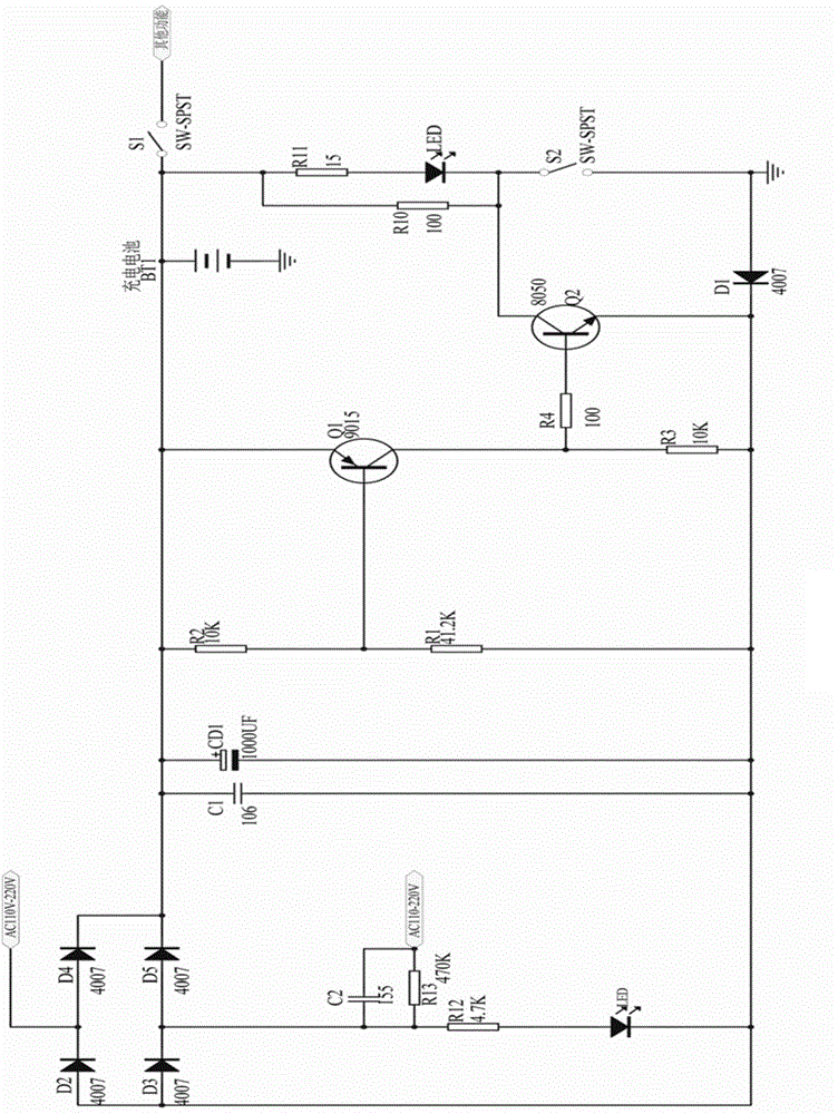
[0041] Such as image 3 As shown, this embodiment is the same as that of embodiment 1 except that the setting position of rectifier diode D1 and the models of first transistor Q1 and second transistor Q2 are different from embodiment 1, which is a modification of embodiment 1. Program. Wherein, the models of the first transistor Q1 and the second transistor Q2 are respectively a 9015 model PNP transistor and an 8050 model NPN transistor.

[0042] The positive terminal of the rectifier diode D1 in this embodiment is grounded; the first resistor R1 and the second resistor R2 are connected in series to form a voltage divider circuit between the output terminal of the rectifier circuit and the negative terminal of the rectifier diode D1, and the first transistor Q1 The base is connected to the connection point of the first resistor R1 and the second resistor R2, the emitter is connected to the output terminal of the rectifier circuit, one of the collectors is connected to the neg...


PUM


Abstract

The invention provides a charging protection circuit which is simple in structure, low in cost and capable of effectively leading charging current to other functional devices after a battery is fully charged and is used for capacitor voltage reduction. A reverse switching element, a battery overcharge detection circuit and a battery overcharge shunt circuit are arranged between a rectifying circuit and a battery charging circuit. By means of the charging protection circuit, when the charging battery is fully charged, in other words, when the set electricity storage amount upper limit value is achieved, power supply current is led to circuits of the other functional devices, such as LED display lamps, heaters and small motors or a small part of functional devices, arranged on a product, and therefore the voltage of the charging battery can be lower than or equal to the set value in the charging process. It is ensured that no overcharge phenomenon can happen to the charging battery, the charging battery is effectively protected, and the service life of the charging battery is greatly prolonged. The charging protection circuit is simple in structure, only dozens of small-power components are used, the product performance is improved, and the material cost can be effectively reduced.

Description

technical field [0001] The invention relates to a charging protection circuit, in particular to an overcharge protection circuit adopting a capacitor step-down charging circuit. Background technique [0002] The conventional way to convert AC power to low-voltage DC is to use a transformer to step down and then rectify and filter. When limited by factors such as size and cost, the simplest and most practical method is to use a capacitor step-down power supply. [0003] In the prior art, small household appliances that use capacitor step-down charging, such as flashlights, card speakers, Bluetooth speakers, radios, etc., all use overcharge-resistant lead-acid batteries or nickel-cadmium batteries, basically without charging protection circuits. Capacitor step-down charging uses a common battery charging protection circuit, and a high-power voltage stabilizing device must be added. There is following deficiency in above-mentioned structure: [0004] 1) The overcharge-resista...

Claims


Application Information

Patent Timeline
Patent Type & Authority Applications(China)
IPC IPC(8): H02J7/00H02J7/02
CPCH02J7/00
Inventor 申勇兵
Owner 怀化市红圳电子科技有限责任公司
Why Eureka
Try Eureka