
Power converters and compensation circuits thereof

A compensation circuit and boost converter technology, applied in the field of compensation circuits, can solve problems such as difficulty in compensating boost converters and buck-boost converters

Inactive Publication Date: 2015-05-13
TEXAS INSTR INC
View PDF6 Cites 3 Cited by
  • Summary
  • Abstract
  • Description
  • Claims
  • Application Information

AI Technical Summary

Problems solved by technology

The presence of RHPZ makes it difficult to compensate boost and buck-boost converters compared to buck converter compensation

Method used


Image

  • Power converters and compensation circuits thereof
  • Power converters and compensation circuits thereof
  • Power converters and compensation circuits thereof

Examples


Embodiment Construction

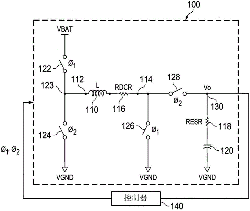
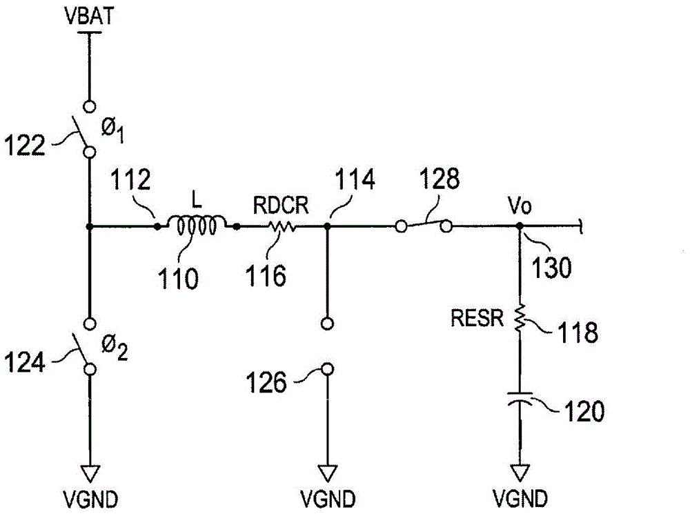
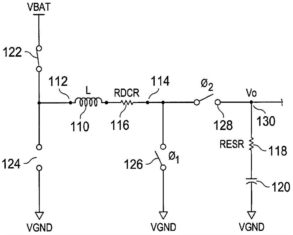
[0017] In the following detailed description, numerous specific details are set forth in order to provide a thorough understanding of the present technology. However, the techniques of the present invention may be practiced without these specific details. In other instances, well-known methods, procedures, components, and circuits have not been described in detail so as not to unnecessarily obscure aspects of the example embodiments presented herein. In addition, it should be noted that structures and devices are shown in block diagram form in order to avoid obscuring the invention.

[0018] Reference throughout this specification to "one embodiment" or "an embodiment" means that a particular feature, structure, or characteristic described in connection with the embodiment is included in at least one embodiment of the present invention. The appearances of the phrase "in one embodiment" in various places in this specification are not necessarily all referring to the same embod...


PUM


Abstract

In an embodiment, a circuit includes a Direct Current (DC)-DC buck-boost converter and a controller. The controller includes an error amplifier configured to receive a feedback signal responsive to an output signal of the buck-boost converter. The error amplifier is configured to compare the feedback signal and a reference signal to generate an error signal. The controller includes a modulator circuit that is configured to receive the error signal and compare the error signal with a periodic ramp signal to generate a modulated signal. The controller further includes a digital logic block to generate switching signals in response to the modulated signal that is fed to the buck-boost converter to control the output signal of the buck-boost converter. The controller includes a capacitance multiplier circuit coupled to the output of the error amplifier to configure a dominant pole so as to compensate the buck-boost converter.

Description

technical field [0001] The present invention relates generally to electrical and electronic circuits, and more particularly to power converters and compensation circuits used in such power converters. Background technique [0002] According to example scenarios, switching regulators (eg, power converters) are implemented in various electrical and electronic devices. With the increasing use of portable and handheld devices such as mobile phones, personal digital assistants (PDAs), global positioning system (GPS) devices, etc., a single power supply battery can be implemented in such devices. Such devices may have various components including different power parameters; for example, certain components of the devices may be configured to utilize a 3.6 volt (V) power supply, and some components may be configured to utilize a 3.3V power supply supply, and some components can be configured to utilize a 1.8V power supply. All of these various power supply levels are generated fro...

Claims


Application Information

Patent Timeline
IPC IPC(8): H02M3/155
CPCH02M3/1582
Inventor 斯里尼瓦斯·文卡塔·维拉姆雷迪素提希尔·波拉鲁图
Owner TEXAS INSTR INC
Learn More