A Control Strategy of Dynamic Voltage Stabilizer for Distribution Network
A dynamic voltage and control strategy technology, applied in the direction of AC network voltage adjustment, AC network flicker reduction, etc., can solve the problems of limiting the dynamic response speed of DVR, weakening the robustness of equipment, and being unable to meet the compensation voltage without static error tracking. Achieve the effect of improving the transient response characteristics, solving the complex calculation of coordinate changes, and suppressing the underdamping effect
- Summary
- Abstract
- Description
- Claims
- Application Information
AI Technical Summary
Problems solved by technology
Method used
Image
Examples
Embodiment example 1
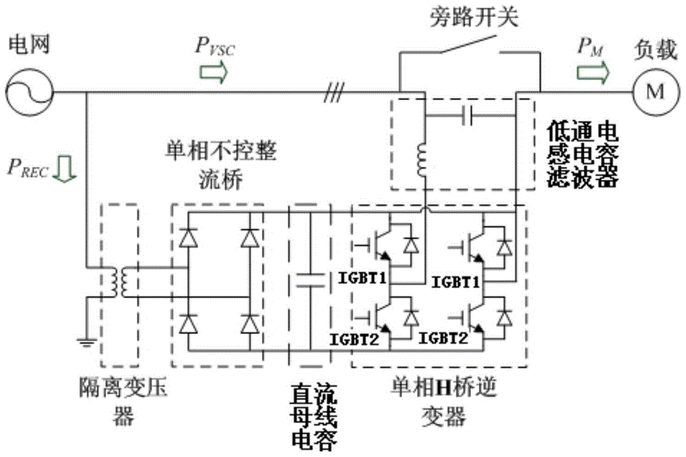
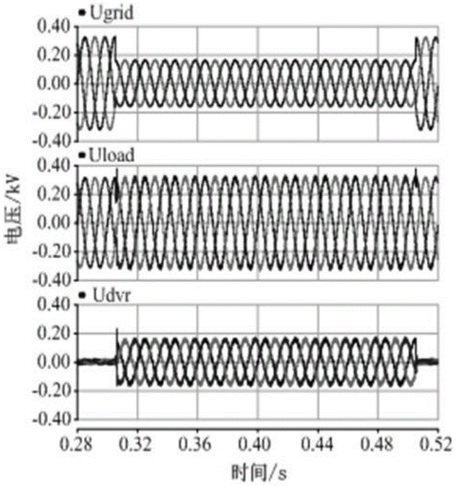
[0047] Such as image 3 with 4 The PSCAD\EMTDC simulation diagrams of two different scenarios of three-phase symmetrical voltage drop and three-phase asymmetrical voltage drop under the dynamic voltage stabilizer without phase jump are shown, as shown Figure 5 The PSCAD\EMTDC simulation diagram of the asymmetrical voltage drop under the phase jump is shown as shown to further describe the specific working process of the present invention. Since the dynamic voltage stabilizer uses three single-phase structures, the three phases are independent control, so only the single-phase operation process is given, and at the same time image 3 , Figure 4 with Figure 5 The simulated waveform in the first scenario of the three different scenarios is taken as an example for detailed description.
[0048] Simulation time: 0.52s, IGBT switching frequency 3.2kHz, system frequency 50Hz; fault start time 0.305s, fault duration 0.2s; fault type: three-phase symmetrical voltage drop 50%.
...
Embodiment example 2
[0053] In order to further verify the engineering practicability of this device, an experimental platform composed of DVR, asynchronous motor and voltage drop generator was established, such as Image 6 with 7 The expanded waveforms at the beginning and end of grid voltage sag are given.
[0054] Source 1 is the grid voltage, source 2 is the output voltage of the DVR, and source 3 is the load terminal voltage; during operation, the grid voltage drops with a time span of about 1s, and its peak value drops from 300V to 110V, and the voltage drop occurs After that, the DVR responds quickly and maintains the load terminal voltage at the normal level.
[0055] The experimental waveforms confirmed that when the grid voltage dropped to 30% of the rated value, the DVR completed the response within 2ms, and there was no voltage oscillation phenomenon easily caused by the system under-damping, the dynamic characteristics were good, and the compensation effect was verified after stabili...
PUM
 Abstract
Description
Claims
Application Information
 - R&D
- Intellectual Property
- Life Sciences
- Materials
- Tech Scout
- Unparalleled Data Quality
- Higher Quality Content
- 60% Fewer Hallucinations
Browse by: Latest US Patents, China's latest patents, Technical Efficacy Thesaurus, Application Domain, Technology Topic, Popular Technical Reports.
© 2025 PatSnap. All rights reserved.Legal|Privacy policy|Modern Slavery Act Transparency Statement|Sitemap|About US| Contact US: help@patsnap.com


