Spark testing apparatus

A technology of equipment, electric sparks, used in mechanical equipment, mining equipment, preventing sparks, etc.

Inactive Publication Date: 2015-05-13
CMTE DEV LTD
View PDF6 Cites 4 Cited by
  • Summary
  • Abstract
  • Description
  • Claims
  • Application Information

AI Technical Summary

Problems solved by technology

Cadmium disks used to generate sparks and flammable gases surrounding equipment are hazardous substances causing health and safety concerns

Method used


Image

  • Spark testing apparatus
  • Spark testing apparatus
  • Spark testing apparatus

Examples


Embodiment Construction

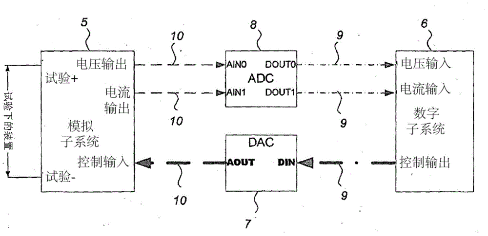
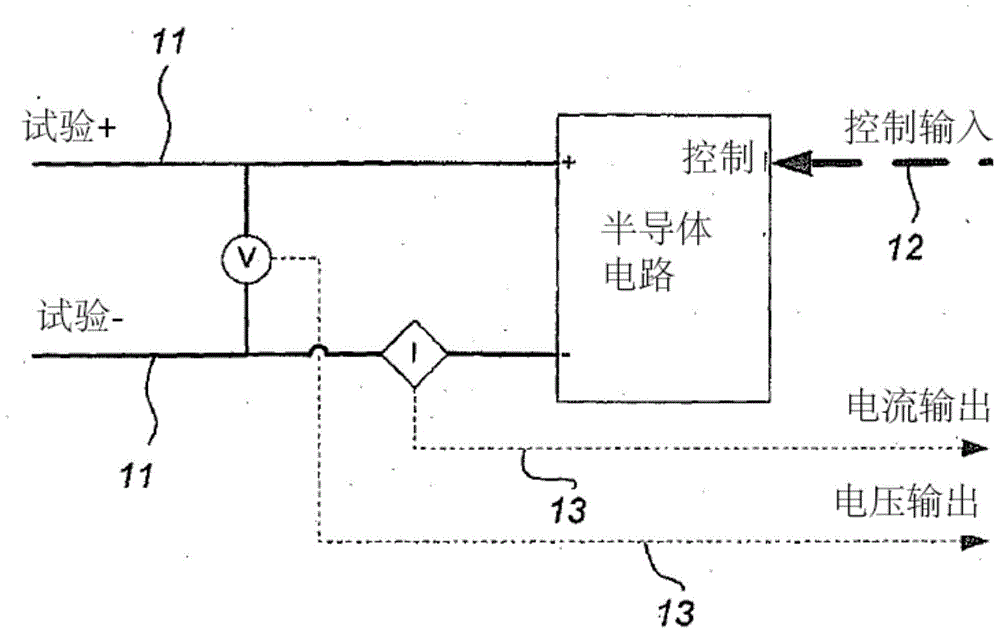
[0025] In one preferred form of the invention, the prior art mechanical STA device is replaced by a circuit that generates and measures the effect on the characteristics of the spark previously generated by the mechanical spark test device (STA).

[0026] STA randomly generates sparks, not sure when the explosion will occur (if it happens at all). Since the STA under the test is connected to the energy source as a load, only the electrical characteristics of the spark generated by it can be analyzed.

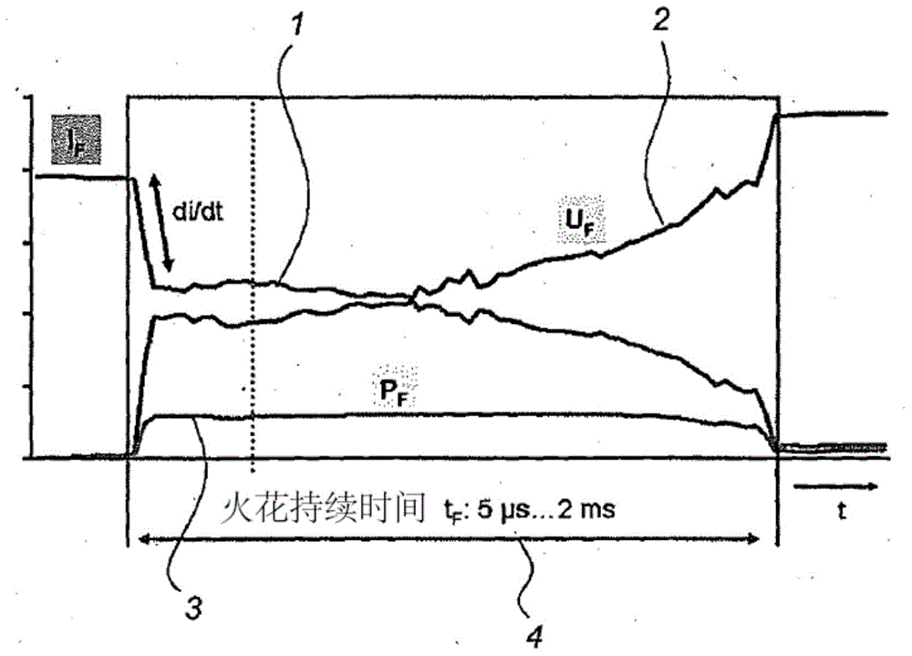
[0027] Specifically, sparks can be considered as time-varying electrical loads. This means that the voltage across the spark and the current through the spark for the duration of the spark fully describe the spark. The electrical signature of a typical open circuit spark is at figure 1 shown in figure 1 The current 1 characteristic and the voltage 2 characteristic and the instantaneous power 3 within the duration of the spark represented by the time span 4 are shown in .

[...


PUM


Abstract

The invention provides a method and apparatus for electronically testing the safety of sources of energy such as electrical circuits, in explosive atmospheres such as high risk mining situations, using an electronic spark tester (EST) in place of the known mechanical spark test apparatus (STA). The EST typically uses an analogue subsystem (5) and a digital subsystem (6) connected by a digital to analogue converter (7) and an analogue to digital connector (8) to apply a simulated spark load to the energy source and measure the time varying current response to that load.

Description

technical field [0001] The present invention relates to a spark test apparatus and is specifically designed not only for assessing the safety of energy sources used in high risk mining situations. Background technique [0002] There are many situations where an explosive atmosphere exists and there is a safety risk if these gases come into contact with an energy source (such as an explosion from eg an electrical circuit). The concept of "intrinsic safety" is also considered as a method of instrument protection in this explosive atmosphere. Protection is achieved by designing the energy source so that it cannot produce an explosive spark. This is achieved by limiting the power that the source can provide either always or when a false start is detected. [0003] In the past, energy sources with simple electrical characteristics have been shown to be intrinsically safe based solely on these characteristics through the use of evaluation curves. However, many devices have more...

Claims


Application Information

Patent Timeline
Patent Type & Authority Applications(China)
IPC IPC(8): G01R27/30H02H1/00G06F11/26E21F9/00F02B77/08E21F17/18
CPCG01R31/001G01R19/145
Inventor 拉吉夫·钱德拉·谢加爱德华·加斯·普瑞康巴伦德·雅各布斯·皮纳尔保罗·约翰·艾伦·莱沃
Owner CMTE DEV LTD
Why Eureka
Try Eureka