Regulated power supply assembly for use in electrical switch

A regulated power supply, electrical switch technology, applied to electrical components, emergency protection circuit devices for limiting overcurrent/overvoltage, circuits, etc. Contact bounce and other issues

Inactive Publication Date: 2015-05-13
SIEMENS AG
View PDF5 Cites 1 Cited by
  • Summary
  • Abstract
  • Description
  • Claims
  • Application Information

AI Technical Summary

Problems solved by technology

This mechanical stress adversely affects the service life of the electrical switch
In extreme cases, this uncontrolled opening can adversely cause the movable contacts to spring back towards the corresponding fixed contacts, which can undesirably cause arcing between the movable and fixed contacts
[0013] It is now understood that it is difficult to ensure that the cut-off operation is performed in such a way as to meet the conflicting requirements: to achieve rapid opening of electrical switches, but to achieve these requirements, to reduce mechanical stress caused by the energy supplied to the various moving elements damage
[0014] Various prior art electrical switches focus only on achieving quick opening during the cut-off operation without providing any means to eliminate the mechanical damage resulting therefrom

Method used


Image

  • Regulated power supply assembly for use in electrical switch
  • Regulated power supply assembly for use in electrical switch
  • Regulated power supply assembly for use in electrical switch

Examples


Embodiment Construction

[0034] Various embodiments are described with reference to the drawings, wherein like reference numerals are used to refer to like parts throughout. In the following description, for purposes of explanation, numerous specific details are provided in order to provide a thorough understanding of one or more implementations. It is evident that such embodiments may be practiced without these specific details.

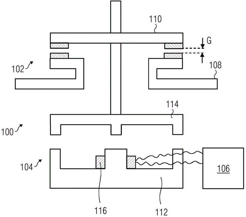
[0035] refer to figure 1 , a schematic diagram of an electrical switch 100 is provided.

[0036] The electrical switch 100 includes a contact assembly 102 , an electromagnetic assembly 104 and a regulated power supply assembly 106 . It should be noted that the electrical switch 100 includes various other components in addition to those shown in the adjacent figures. However, for reasons of clarity, these additional elements are not shown in adjacent figures.

[0037] The contact assembly 102 includes at least one pair of stationary contacts 108 and at least one correspo...


PUM


Abstract

Regulated power supply assembly for use in electrical switch A regulated power supply assembly (106) suitable for use in an electrical switch (100) is disclosed. The regulated power supply assembly regulates an excitation current provided to an electromagnetic assembly (104) within the electrical switch. The regulated power supply assembly includes switching means (206), free-wheeling means (208), and controlling means (210). The switching means regulates an excitation current provided to an electromagnetic assembly. The free-wheeling means provide a freewheeling current flow path for the excitation current. The controlling means are configured for regulating the switching means and the free-wheeling means such as to regulate the excitation current during transition from the closed position to the open position.

Description

technical field [0001] The present invention generally relates to an electrical switch for opening and closing a conductive path between a power source and an electrical load. In particular, the invention relates to a regulated power supply assembly suitable for operating such an electrical switch. Background technique [0002] In a conventional electrical switch, at least one movable contact is displaced relative to at least one pair of fixed contacts so as to establish or interrupt a conductive path between the source-side and load-side fixed contacts. The fixed contacts on the power supply side and the load side are respectively connected to the power supply and the electric load. A solenoid assembly is included to provide the actuation force to cause the movable contact to move on demand from the open position to the closed position during the make operation. In addition, a biasing mechanism is included to provide a biasing force for returning the movable contact from ...

Claims


Application Information

Patent Timeline
Patent Type & Authority Applications(China)
IPC IPC(8): H01H47/32H02H9/04
CPCH01H47/325
Inventor 维贾伊·利马耶
Owner SIEMENS AG
Why Eureka
Try Eureka