
A manipulator structure for automatic loading and unloading of punch presses

A technology of automatic loading and unloading, manipulator, applied in metal processing equipment, feeding device, peeling device, etc., can solve the problems of frequent stamping die change, affecting manual operation space, frequent manual operation in small batches, etc., to achieve the effect of rapid disassembly

Active Publication Date: 2015-07-29
SICHUAN CHANGHONG ELECTRIC CO LTD
View PDF7 Cites 0 Cited by
  • Summary
  • Abstract
  • Description
  • Claims
  • Application Information

AI Technical Summary

Problems solved by technology

However, the installation of this structure manipulator is greatly affected by the space between punching machines, and the intermediate transition mechanism is a permanent fixed connection, which affects the development of new products, trial production and manual operation space during mold replacement.
At present, the market demand is changing, new products are constantly being developed and trial-produced, and the products are produced in small quantities and diversely. In the production process, stamping dies are frequently changed, and small batches of manual operations are frequent.
The manipulator with the existing structure can no longer meet the requirements of automatic loading and unloading of the punch press

Method used


Image

  • A manipulator structure for automatic loading and unloading of punch presses
  • A manipulator structure for automatic loading and unloading of punch presses

Examples


Embodiment Construction

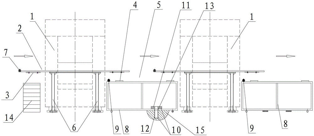
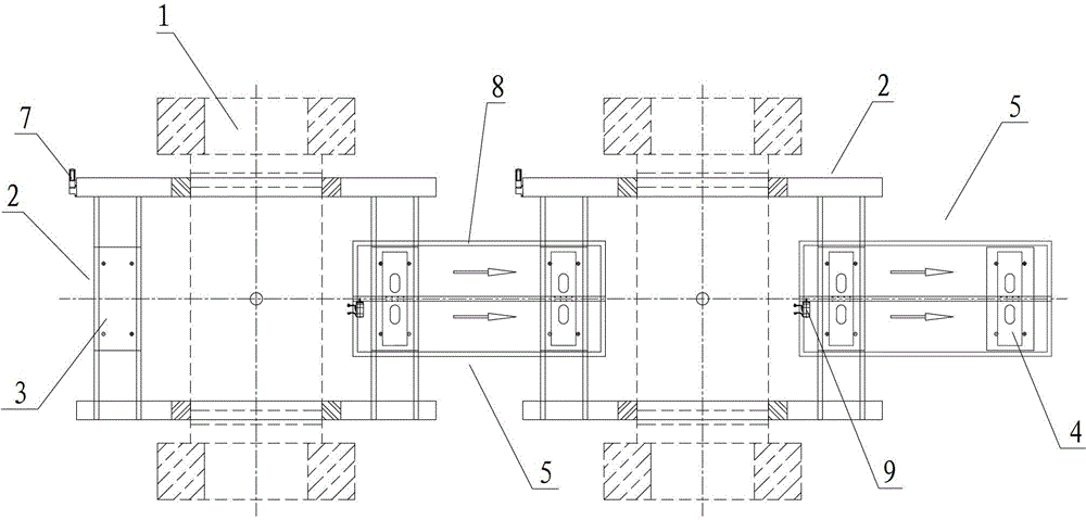
[0015] Such as figure 1 , figure 2 Shown is a method provided by the present invention, which can ensure the flexible connection of any number of punches during mass production, and can ensure that the flexible connection mechanism can be quickly removed for the automatic up and down of punches during small batch manual production or mold replacement. Material manipulator structure. The manipulator structure includes a manipulator body 2 located on both sides of the workbench of the punch press 1, and a transfer module 3 is respectively installed on the input end and the output end of the manipulator body 2, and also includes a manipulator on the input end and the output end respectively. A flexible transfer trolley 5 with a transmission module 4 installed, the flexible transmission trolley 5 is detachably installed between two adjacent punches 1, and the transmission module 4 on its delivery end and output end is respectively connected to the adjacent two punches 1 The tra...


PUM


Abstract

The invention discloses a manipulator structure, in particular to the manipulator structure for automatic material loading and unloading of a punch press, which belongs to the field of an electronic product production equipment technology. With the provision of the manipulator structure for automatic material loading and unloading of the punch press, any number of punch presses can be flexibly connected while the mass production is performed, and flexible connection mechanisms are quickly removed when a small amount of manual production is performed or a mould is changed. The manipulator structure comprises manipulator bodies at two sides of an operating platform of the punch press, transferring modules are arranged at the input ends and the output ends of the manipulator bodies; the manipulator structure further comprises a flexible transmission trolley, the input end and the output end of the manipulator trolley are respectively provided with transmission modules, the flexible transmission trolley is detachably arranged between two adjacent punch presses, the transmission modules at the transmission end and the output end of the flexible transmission module are respectively applicable to the transferring modules on the manipulator bodies at the sides of the operating tables of two adjacent punch presses.

Description

technical field [0001] The invention relates to a manipulator structure, in particular to a manipulator structure for automatic loading and unloading of punch presses, and belongs to the technical field of electronic product production equipment. Background technique [0002] At present, the metal stamping production of large punching machines is mostly done by manual operation of punching machines for manual loading and unloading, especially for the stamping production of large PDP backplanes. In this way, each punching machine must have two operators, and the workpieces are also transferred manually between different processes, so the production efficiency is low and the safety is poor. [0003] In order to improve the production efficiency of the punch press, the designers have developed a series of automatic equipment for automatic loading and unloading, such as the automatic transfer manipulator for stamping, in view of the current situation of domestic stamping product...

Claims


Application Information

Patent Timeline
Patent Type & Authority Patents(China)
IPC IPC(8): B21D43/10B21D45/00
Inventor 刘兵蒲显西潘晓勇姚国红
Owner SICHUAN CHANGHONG ELECTRIC CO LTD
Learn More