Electromechanical power steering with backlash compensation for worm gears

A technology of power steering and power steering, which is applied in the direction of power steering mechanism, electric steering mechanism, steering mechanism, etc., which can solve the problem of high force or moment, and achieve the effect of quick removal response and flexible settability

Active Publication Date: 2016-04-06
THYSSENKRUPP PRESTA AG
View PDF8 Cites 0 Cited by
  • Summary
  • Abstract
  • Description
  • Claims
  • Application Information

AI Technical Summary

Problems solved by technology

However, the forces or moments required for this which must ultimately be applied via the tooth engagement are relatively high, since the plain bearing arrangement of the cam in the transmission housing has a high breaking torque

Method used


Image

  • Electromechanical power steering with backlash compensation for worm gears
  • Electromechanical power steering with backlash compensation for worm gears
  • Electromechanical power steering with backlash compensation for worm gears

Examples


Embodiment Construction

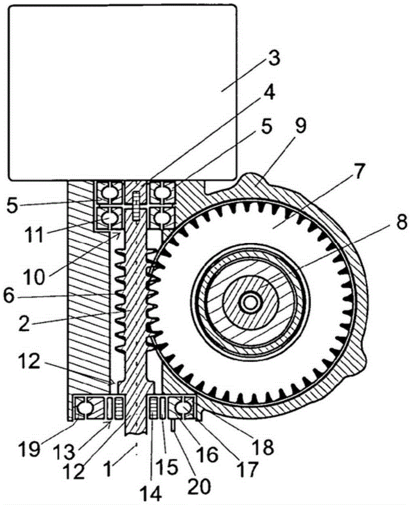
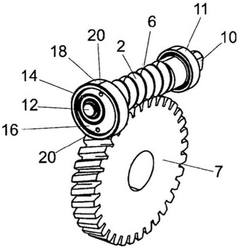
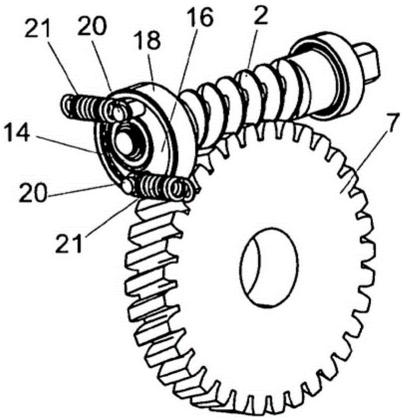
[0021] figure 1 A longitudinal section of the transmission of the electromechanical power steering is shown and extends along the axis of rotation 1 of the worm shaft 2 driven by the electric motor 3 . The electric motor 3 has a motor shaft 4 which is coupled in a rotationally fixed manner to the worm shaft 2 via a flexible coupling 5 . The worm shaft 2 meshes with a worm wheel 7 via a worm toothing 6 . The worm gear 7 is in turn connected in a rotationally fixed manner to a steering shaft 8 which extends between the not shown steering wheels of the motor vehicle and the actual steering gear.

[0022] The structural elements are accommodated in a common transmission housing 9 .

[0023] The mounting of the worm shaft 2 in the housing 9 takes place in a conventional roller bearing 11 designed as a ball bearing at the motor-side end 10 of the worm shaft 2 . The ball bearing 11 is designed such that a small axial movement of the worm shaft 2 relative to the housing 9 and a sma...


PUM


Abstract

The invention relates to an electromechanical power steering with a booster motor (1) driving a worm shaft (2) which meshes with a worm wheel (7) arranged on the steering shaft (8), wherein the worm wheel (7) is operatively connected to the input shaft of the steering gear, and wherein the worm shaft (2) and the steering shaft (8) are rotatably mounted in a common gear housing (9), in said power steering (2) have a free end (12) away from the motor, said end being mounted in a rolling bearing (13) with an inner ring (14), rolling elements (15) and an intermediate ring (16), wherein the intermediate ring has The inner running surface for the rolling elements (15) and the outer rolling surface for the outer rolling elements (17), and the outer and inner running surfaces of the intermediate ring (16) arranged eccentrically with respect to each other.

Description

technical field [0001] The invention relates to an electromechanical power steering. Background technique [0002] When mounting the shaft, it is conceivable and feasible to use a plain bearing of an outer ring with an outer peripheral surface which is arranged eccentrically with respect to the bearing surface. However, such bearing arrangements are only suitable for rotating shafts. The rotating shaft has the disadvantage that the shaft is usually at a standstill because the slide bearings have a high breakaway torque. In principle, the slide bearings also require monitoring and continuous lubrication during operation. Therefore, plain bearing arrangements are not used for mounting the drive shaft of the electromechanical power steering. [0003] European patent EP1727723B1 shows a ball bearing in an electromechanical power steering with an eccentric outer ring by means of which the position of a shaft mounted in the bearing can be set. After setting, the outer bearing ...

Claims


Application Information

Patent Timeline
Patent Type & Authority Patents(China)
IPC IPC(8): B62D5/04F16H57/022
CPCB62D5/0409F16H2057/0224F16H2057/0213F16H2057/02082F16H55/24B62D5/0454
Inventor 罗伯特·加莱尔
Owner THYSSENKRUPP PRESTA AG
Why Eureka
Try Eureka