Crash sensor and intelligent dust collector robot

A technology of collision sensor and robot body, which is applied in the direction of vacuum cleaners, cleaning equipment, household appliances, etc., to achieve the effect of sensitive collision detection, simple structure, random installation position and fixing method

Active Publication Date: 2015-05-20
SHENYANG SIASUN ROBOT & AUTOMATION
10 Cites 10 Cited by

AI-Extracted Technical Summary

Problems solved by technology

[0004] The object of the present invention is to provide a collision sensor and an intelligent vacuum cleaner robot in view of the defects in the prior art. On the basis of not affecting the o...

Abstract

The invention provides a crash sensor and an intelligent dust collector robot. The crash sensor comprises common rubber, electroconductive rubber and a flexible circuit board. The flexible circuit board is provided with two independent electroconductive loops, one side surface of the electroconductive rubber is fixed on the common rubber, the other side surface of the electroconductive rubber is arranged to face the flexible circuit board, and a gap is formed between the electroconductive rubber and the flexible circuit board. According to the crash sensor and the intelligent dust collector robot, a proper circuit wiring form is made on the flexible circuit board, the outer side of the flexible circuit board is covered with the electroconductive rubber, the electroconductive rubber makes contact with the flexible circuit board in crash, and therefore circuit breakover achieves the purpose of detecting the crash. According to the crash sensor and the intelligent dust collector robot, a crash detecting function of the intelligent root can be achieved. Compared with an existing crash sensor, the crash sensor and the intelligent dust collector robot has the advantages that the structure is simpler, mounting positions and fixing ways are freer, crash detection is more sensitive, the range is wider, and dead angles do not exist.

Application Domain

Suction cleanersForce measurement by elastic gauge deformation

Technology Topic

Flexible circuitsDust collector +1

Image

  • Crash sensor and intelligent dust collector robot
  • Crash sensor and intelligent dust collector robot
  • Crash sensor and intelligent dust collector robot

Examples

  • Experimental program(2)

Example Embodiment

[0021] Example one
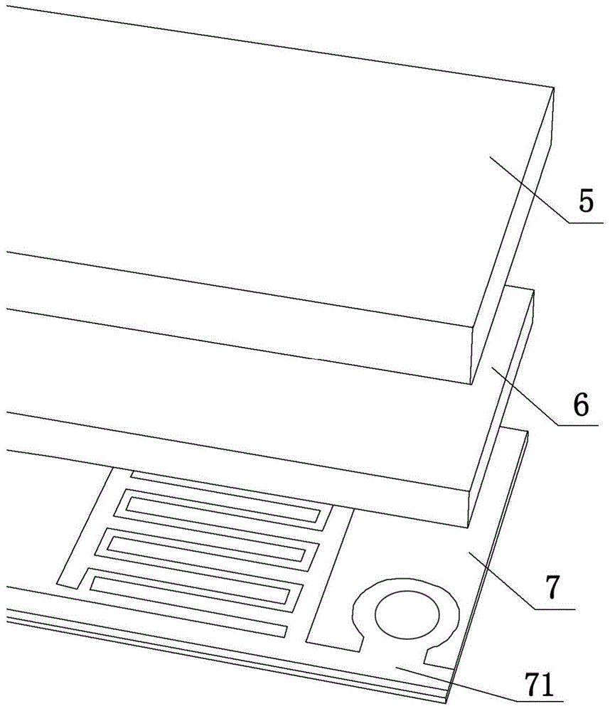
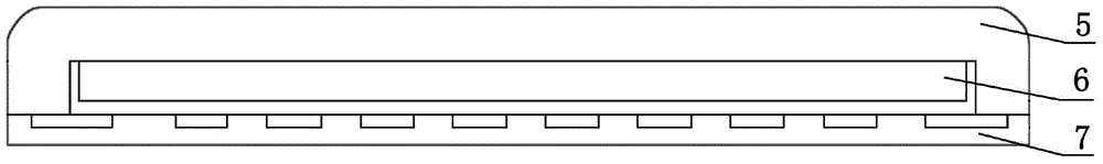
[0022] The basic structure of a collision sensor provided by an embodiment of the present invention consists of three parts, such as figure 2 As shown, from the outer layer to the inner layer are ordinary rubber 5, conductive rubber 6 and flexible circuit board 7, respectively. The flexible circuit board 7 is provided with two independent conductive loops 71, one side of the conductive rubber 6 is fixed on the common rubber 5, and the other side of the conductive rubber 6 is set toward the flexible circuit board 7.
[0023] Ordinary rubber 5 is used as a cushioning part that contacts with obstacles in collision, and its shape is designed into a smooth shape, such as image 3 As shown, the edges and corners of the outer side have smooth chamfers, which are beautiful and will not damage other objects during collision. A groove is designed in the middle of the inner side of the ordinary rubber 5 to fix the conductive rubber 6. The guide rubber 6 is used as a conductive switch to connect the two conductive loops 71 on the flexible circuit board 7. In order to prevent the two conductive loops 71 from being conducted when there is no collision, the thickness of the conductive rubber 6 here is smaller than that of ordinary rubber 5 The depth of the middle groove, and use an appropriate adhesive to fix the conductive rubber 6 on the bottom of the groove of the ordinary rubber 5. In this way, the edge of the groove on the ordinary rubber 5 is supported on the flexible circuit board 7 to form a certain gap between the conductive rubber 6 and the flexible circuit board 7.
[0024] Such as Figure 4 As shown, the two conductive loops 71 on the flexible circuit board 7 respectively include a main circuit 711 and a comb-shaped conductive circuit 712. The main lines 711 of the two conductive loops 71 penetrate the flexible circuit board 7 along the length direction and are arranged in parallel to each other. The comb-shaped conductive line 712 includes a plurality of parallel strip lines and a section of connecting strip lines; the plurality of parallel strip lines are arranged in parallel at equal intervals along the width direction of the flexible circuit board 7; the connecting strip lines connect the The multiple parallel strip lines are connected to the main line 711, and the multiple parallel strip lines are located on the same side of the connected strip lines, forming a comb shape. The comb-shaped conductive lines 712 on the two conductive loops 71 are arranged opposite to each other, and the parallel strip lines in the two comb-shaped conductive lines 712 opposite to each other are intersected and staggered, closely interlaced, but are not connected to each other.
[0025] Such as Figure 5 As shown, when the collision sensor hits the obstacle 8, the ordinary rubber 5 is first squeezed and deformed, and the conductive rubber 6 on its inner side is deformed and squeezed onto the flexible circuit board 7. The two groups on the flexible circuit board 7 The comb-shaped conductive line 712 on the conductive loop 71 will be turned on, thus realizing the function of detecting collision.

Example Embodiment

[0026] Example two
[0027] The invention can be applied to a smart vacuum cleaner robot, replacing the traditional form of detecting collisions through micro switches.
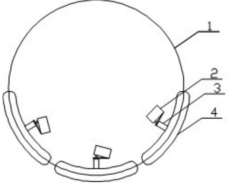
[0028] Such as Image 6 As shown, an intelligent vacuum cleaner robot provided by an embodiment of the present invention includes a robot body 91 and a plurality of collision sensors 92. The robot body 91 is a cylinder, and the multiple collision sensors 92 are installed around the side of the robot body.
[0029] In the embodiment of the present invention, six collision sensors 92 are installed around the robot body 91, so that when the smart vacuum cleaner robot collides with an obstacle, it can react accordingly by distinguishing the collision position.

PUM

no PUM

Description & Claims & Application Information

We can also present the details of the Description, Claims and Application information to help users get a comprehensive understanding of the technical details of the patent, such as background art, summary of invention, brief description of drawings, description of embodiments, and other original content. On the other hand, users can also determine the specific scope of protection of the technology through the list of claims; as well as understand the changes in the life cycle of the technology with the presentation of the patent timeline. Login to view more.

Similar technology patents

Photoelectric sensor for position of sun

InactiveCN101650173AEffective tracking range expandedSimple structure
Owner:WUHAN UNIV OF TECH

Magnetic cooling apparatus and control method thereof

ActiveUS20130180263A1simple structure
Owner:SAMSUNG ELECTRONICS CO LTD

Dual-Drivetrain of Power-Assist Vehicle

InactiveUS20100181130A1enhance uphill momentumsimple structure
Owner:CHOU WEN CHENG

Classification and recommendation of technical efficacy words

Why Eureka
Try Eureka