

Jig for assembling main roller shafts of fork carrier of forklift
A technology for a fork frame and a roller shaft is applied in the field of assembling molds for the main roller shaft of a forklift fork frame, which can solve the problems of low production efficiency, large shape and position tolerance, complicated correction procedures, etc., and achieves convenient demoulding, high precision, The effect of low labor intensity
- Summary
- Abstract
- Description
- Claims
- Application Information
AI Technical Summary
Problems solved by technology
Method used
Image

Examples
Embodiment 1
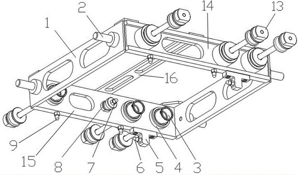
[0032] Example 1: see figure 1 , an assembly mold for the main roller shaft of a forklift fork frame, including a frame 1, a first positioning mechanism 3, and a second positioning mechanism 13;
[0033] The frame 1 is a rectangular frame formed by splicing four side panels;
[0034] The two opposite side plates of the frame 1 are respectively provided with more than two first positioning mechanisms 3 and more than two second positioning mechanisms 13, and the side plates of the frame 1 provided with the first positioning mechanisms 3 are the first side plates 15. The frame 1 side plate provided with the second positioning mechanism 13 is the second side plate 14; the two or more first positioning mechanisms 3 are arranged on the same level, and the first positioning mechanism 3 and the second positioning mechanism 13 are one One correspondence, and the first positioning mechanism 3 and the second positioning mechanism 13 are arranged symmetrically;
[0035] The first posi...
Embodiment 2
[0043] Example 2: The first side plate 15 is provided with three first positioning mechanisms 3 , and the three first positioning mechanisms 3 are set according to the installation position of the main roller shaft 10 , and the rest of the structure is the same as that of the first embodiment.
Embodiment 3
[0044] Example 3: The bottom surface of the first side plate 15 is provided with two third positioning pins 9, and the two third positioning pins 9 are located on the bottom surface of the first side plate 15 on one side of the step seat 5, and are connected with the second positioning pins 6. Two-dimensional positioning is formed, and all the other structures are the same as in Embodiment 1.
[0045] Concrete operation steps of the present invention are as follows:
[0046](1) see Image 6 , the two vertical boards 11 are vertically arranged in the middle of the fork frame 12 as required, and the two vertical boards 11 are arranged symmetrically;
[0047] (2) see Figure 4 , Figure 5 Hold the handle 2 and place the present invention on the fork frame 12 so that the two vertical plates 11 are positioned on the frame 1, and the first side plate 15 and the second side plate 14 of the frame 1 are parallel to the two vertical plates 11 respectively. The second positioning p...
PUM
 Abstract
Description
Claims
Application Information