Tool capable of machining antique damaged veins and plate vein scraper
A squeegee and pattern technology, applied in the field of knives and sheet squeegee machines that can process retro damaged patterns, can solve the problems of high labor intensity, low production efficiency, uneven product quality, etc., to improve work efficiency and reduce labor intensity. , better decorative effect
- Summary
- Abstract
- Description
- Claims
- Application Information
AI Technical Summary
Problems solved by technology
Method used
Image
Examples
Embodiment 1
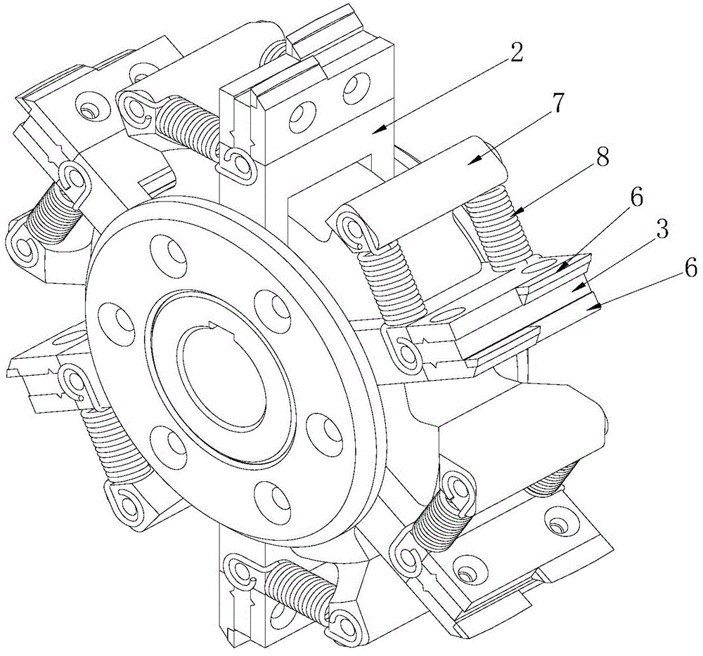
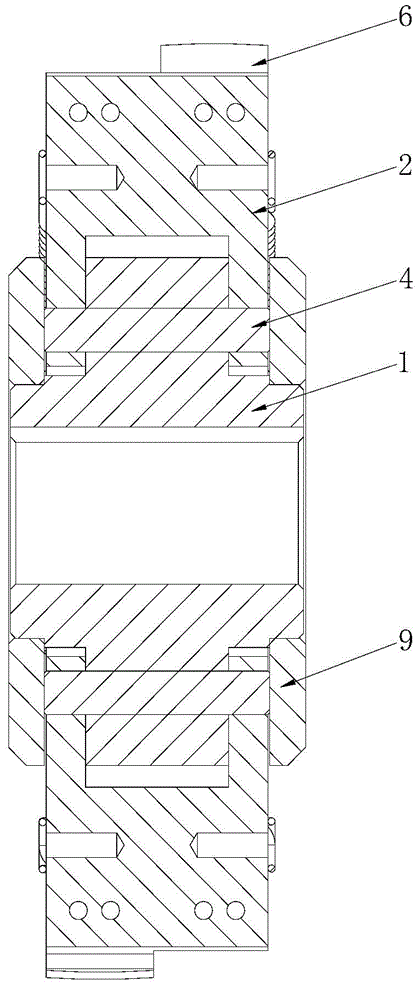
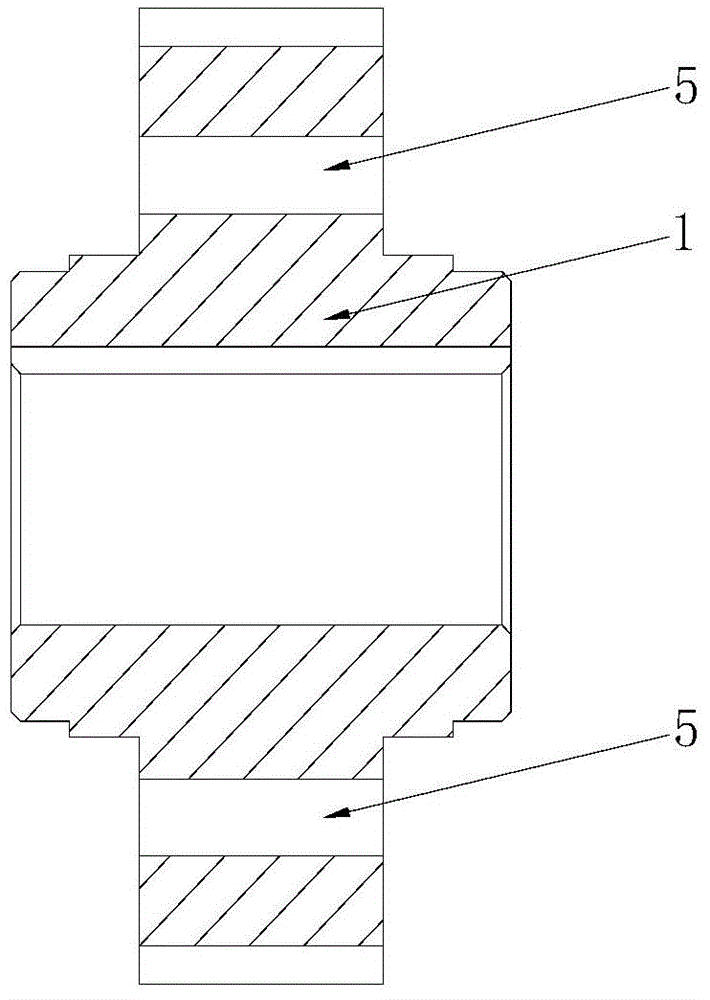
[0047] Such as figure 1 , 2 , The scraper shown in 3 includes a cutter head 1, and the cutter head 1 is provided with 6 knife holders. In the first embodiment, the cutter head 1 is in the shape of a wheel; the cutter holder is composed of a receiving block 2 and a partition block 3 . The positioning pin 4 passes through the positioning hole 5 of the cutterhead 1 and is connected with the receiving block 2, so that the receiving block 2 is connected with the cutterhead 1 and can rotate relative to the cutterhead 1 around the central axis of the positioning hole 5. The partition block 3 is connected with the receiving block 2 and is perpendicular to the receiving block 2 . Scrapers 6 are installed on both sides of the partition block 3 respectively, and the edge lines of the two scrapers 6 are staggered from each other. The cutterhead 1 is also provided with a fixed block 7 which is connected to the receiving block 2 through a tension spring 8 . Both sides of the cutterhead ...
Embodiment 2
[0049] Such as Figure 4 The scratching machine shown includes a frame 10, and a working platform 11 is arranged inside the frame 10. The working platform 11 is provided with 4 scraping units 12, 2 polishing units 13, 7 conveying units 14 and 8 driven units 15. The 4 scraping units 12 are arranged in sequence to form a scraper processing line, 7 conveying units 14 and Eight driven units 15 form a plate conveying device, wherein a scraping unit 12 is located between two adjacent conveying units 14 , and a driven unit 15 is located between the scraping unit 12 and the conveying unit 14 . The two polishing units 13 are sequentially arranged at the most downstream of the working platform 11 .
[0050] Such as figure 1 , 2 , 3, the scraping unit 12 is composed of a scraping device and a two-dimensional driving device, wherein the structure of the scraping device is similar to that of the scraper in Embodiment 1. The scraping device consists of a drive shaft 16 and a cutter head...
Embodiment 3
[0062] The difference between this embodiment 3 and embodiment 1 is that, as Figure 18 As shown, the scrapers 6 are installed on the same side of the partition block 3, and the edge lines of the two scrapers 6 are flush.
PUM
 Abstract
Description
Claims
Application Information
 - R&D
- Intellectual Property
- Life Sciences
- Materials
- Tech Scout
- Unparalleled Data Quality
- Higher Quality Content
- 60% Fewer Hallucinations
Browse by: Latest US Patents, China's latest patents, Technical Efficacy Thesaurus, Application Domain, Technology Topic, Popular Technical Reports.
© 2025 PatSnap. All rights reserved.Legal|Privacy policy|Modern Slavery Act Transparency Statement|Sitemap|About US| Contact US: help@patsnap.com


