Air duct for concrete aggregate silo

A concrete aggregate and air duct technology, which is applied in the field of air ducts, can solve the problems such as the difficulty of achieving heat exchange effect in the wind field, and achieve the effects of significant heat exchange effect, reduced wind resistance, and uniform wind flow field.

Active Publication Date: 2017-03-15
POWERCHINA XIBEI ENG
View PDF7 Cites 0 Cited by
  • Summary
  • Abstract
  • Description
  • Claims
  • Application Information

AI Technical Summary

Problems solved by technology

However, such a heat exchange method is difficult to achieve a good heat exchange effect due to the inhomogeneity of the wind field

Method used


Image

  • Air duct for concrete aggregate silo
  • Air duct for concrete aggregate silo
  • Air duct for concrete aggregate silo

Examples


Embodiment 1

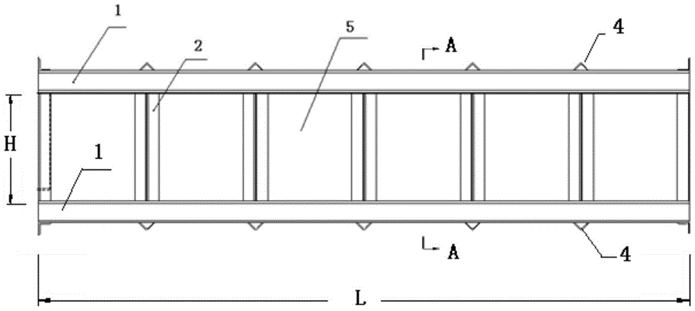
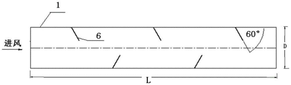
[0023] Embodiment 1, a kind of air duct for concrete aggregate silo, see figure 1 , figure 2 with image 3 , with the rectangular frame as the skeleton of the air duct, the size of the air duct (that is, the internal dimension of the rectangular frame) is L (length) × D (width) × H (height) = 6m × 1m × 1.2m. The inner two sides of the rectangular frame are provided with deflectors 6 obliquely at intervals along the direction of the wind, there is a gap between the two rows of deflectors 6, louvers 5 are arranged between the vertical stiffeners 2 of the rectangular frame, and the top surface of the rectangular frame is provided with There is a top plate 3, the bottom surface is not closed.

[0024] see Figure 7 , the plane size of the silo is a (length) × b (width) = 6m × 4m (b is not marked in the figure); during the operation of the silo, the air duct is always buried in the aggregate, and the bottom surface is formed by accumulation of aggregate. The cross-section of ...

Embodiment 2

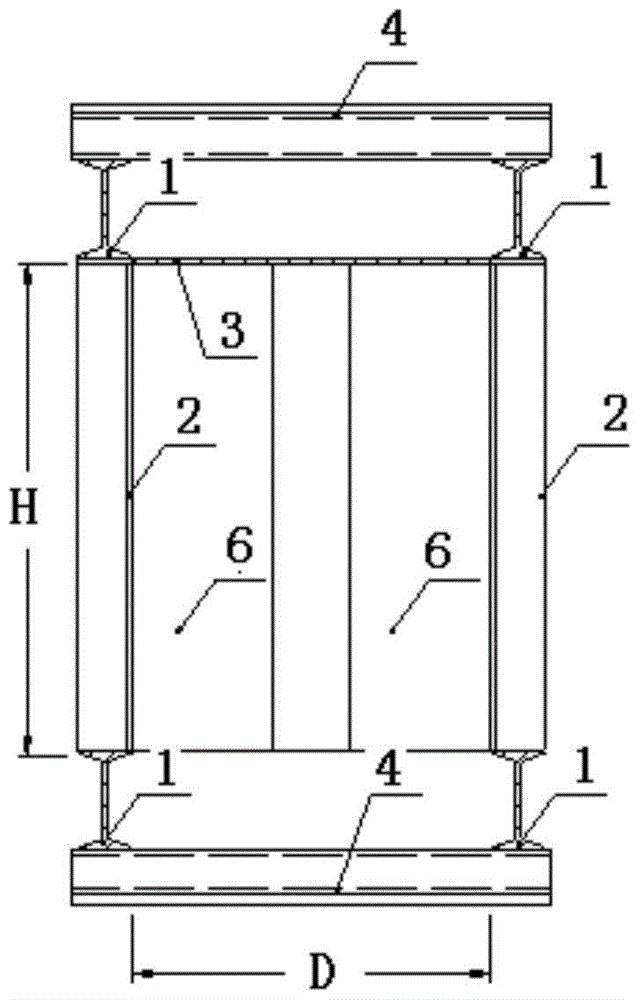
[0027] Example 2, see figure 2 , on the basis of Embodiment 1, in order to ensure that the air duct is sufficient to withstand the impact force and lateral pressure caused by the slow decline of the aggregate in the silo, the rectangular frame of this embodiment is composed of four main beams 1 and the gap between the main beams 1 The vertical stiffeners 2 and transverse stiffeners 4 are formed. The vertical stiffeners 2 are spaced between the upper and lower sides of the main beam 1, and the transverse stiffeners 4 are spaced between the upper two outer sides and the lower two outer sides of the main beam 1.

[0028] In order to further improve the rigidity of the air duct, the main girder 1 is made of I-beam, the vertical stiffener 2 is made of double-angle steel with a distance of 1m, and the transverse stiffener 4 is made of single-angle steel with a distance of 1m. The steel types selected for main girder 1, vertical stiffener 2, and transverse stiffener 4 should be dete...

Embodiment 3

[0029] Example 3, see Figure 4 , The air duct of the present invention is buried in the silo, and the particle size range of the finished aggregate in hydropower projects is 150mm-80mm, 80mm-40mm, 40mm-20mm, and 20mm-5mm. On the basis of Examples 1 and 2, for the aggregates in the silo with aggregate particle sizes of 150mm-80mm, 80mm-40mm, and 40mm-20mm, air outlet holes 7 are evenly arranged on the top plate 3 . In this embodiment, the air outlet holes 7 are circular, with a diameter of ф10, arranged in a quincunx shape, with a pitch of 100 mm and a row pitch of 100 mm, and the row pitch is staggered.

[0030] An air outlet hole 7 with a diameter of ф10 is set on the top plate 3, arranged in a quincunx shape, which can prevent large-grained aggregates from falling into the air duct, and the wind can diffuse upwards into the silo through the air outlet hole 7.

[0031] For aggregates with a particle size of 20mm ~ 5mm, no air outlet 7 is provided on the top plate to prevent...


PUM

PropertyMeasurementUnit
particle diameteraaaaaaaaaa

Abstract

The invention provides an air duct for concrete aggregate storage bin. A rectangular framework is taken as an air duct skeleton, flow guide plates are obliquely arranged on two inner sides of the rectangular framework at intervals along air inlet direction, blind windows are arranged on the vertical surfaces of the two sides of the rectangular framework at intervals, a top plate is arranged at the top surface of the rectangular framework, and the bottom surface of the rectangular framework is not closed. The flow guide plates are obliquely arranged on the inner side vertical surfaces of the rectangular framework at intervals along air inlet direction, and a clearance is left between the opposite flow guide plates. The air duct has a rectangular steel framework structure, and is always arranged in the storage bin, and the air uniformity can be guaranteed through the flow guide plates which are obliquely arranged on two sides of the air duct at intervals. After entering the air duct, air flows out from the air outlet in the top surface and the blind windows on the side vertical surfaces under the action of the flow guide plates, and can conduct uniform heat exchange with aggregates in the storage bin, so that the temperature uniformity of the aggregates can be enhanced. The air duct has strong rigidity and can bear the impact and side pressure caused by the aggregates slowly descending in the storage bin by taking the rectangular framework, made of a steel beam, as the air duct skeleton.

Description

technical field [0001] The invention relates to an air duct, in particular to an air duct used for a concrete aggregate silo. Background technique [0002] In concrete production, there are pre-cooling and pre-heating temperature control requirements at the outlet of the mixing concrete. It is a main measure to cool or heat concrete raw materials, and it is widely used in engineering. [0003] The existing pre-cooling and pre-heating aggregate technologies all use air supply and air distribution devices to send cold or hot air to the aggregate bin, and the wind passes over the surface of the aggregate to exchange heat with the aggregate. However, such a heat exchange method is difficult to achieve a good heat exchange effect due to the inhomogeneity of the wind field. Contents of the invention [0004] The object of the present invention is to provide an air duct for concrete aggregate silos, which effectively improves the air flow field in the silo and improves the heat...

Claims


Application Information

Patent Timeline
Patent Type & Authority Patents(China)
IPC IPC(8): B28C7/00
CPCB28C7/0023
Inventor 关薇康智明李莉卢飞黄天润文宁付廷伍唐大伟郭朝红曾秒
Owner POWERCHINA XIBEI ENG
Why Eureka
Try Eureka