
Bus capacitor discharge system and control method for electric vehicles

A bus capacitor, electric vehicle technology, applied in electric vehicles, electrical devices, vehicle components, etc., can solve the problems that the motor cannot maintain a non-rotating state, violates the driver's driving wishes, and the controller has a small load, and achieves increased self-diagnosis. The effect of function, device selection is easy, and control is simple

Active Publication Date: 2017-02-08
BYD CO LTD
View PDF6 Cites 0 Cited by
  • Summary
  • Abstract
  • Description
  • Claims
  • Application Information

AI Technical Summary

Problems solved by technology

However, this method has the following disadvantages: First, it cannot guarantee that the motor will not rotate under any working conditions. Due to the influence of the detection accuracy of the rotor position of the motor and the influence of control accuracy and errors, the vehicle may be very smooth (for example, the When the vehicle tires are off the ground), the load on the controller is small, and the motor cannot maintain an absolute non-rotating state; second, this control method violates the driver's driving will, and the control module and drive of the drive motor controller The module is used for the power device to drive the motor to work, not for discharging the charge; third, this method can only be used when the motor speed is reduced or static, but not when the motor speed is high. Because the induced electromotive force generated by the motor rotation may be very large at this time, causing the controller to be in the state of motor power generation, unable to discharge the charge

Method used


Image

  • Bus capacitor discharge system and control method for electric vehicles
  • Bus capacitor discharge system and control method for electric vehicles
  • Bus capacitor discharge system and control method for electric vehicles

Examples


Embodiment Construction

[0021] Embodiments of the present invention are described in detail below, examples of which are shown in the drawings, wherein the same or similar reference numerals designate the same or similar elements or elements having the same or similar functions throughout. The embodiments described below by referring to the figures are exemplary and are intended to explain the present invention and should not be construed as limiting the present invention.

[0022] In addition, the terms "first" and "second" are used for descriptive purposes only, and cannot be interpreted as indicating or implying relative importance or implicitly specifying the quantity of indicated technical features. Thus, a feature defined as "first" and "second" may explicitly or implicitly include one or more of these features. In the description of the present invention, "plurality" means two or more, unless otherwise specifically defined.

[0023] In the present invention, unless otherwise clearly specified...


PUM


Abstract

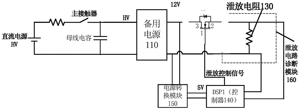
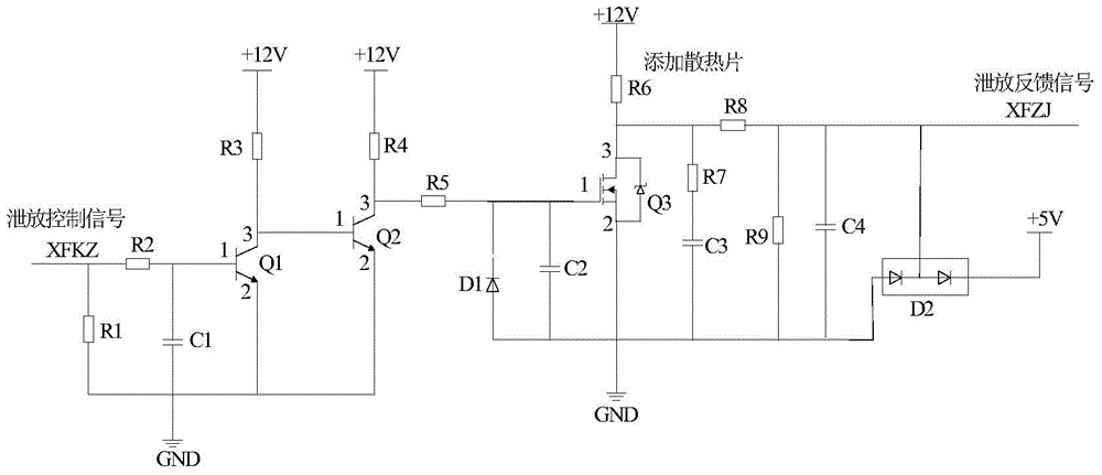
The invention discloses a bus capacitance discharging system for an electric automobile and a control method of the bus capacitance discharging system. The system comprises a reserve power supply, a switch, a discharging resistor, a controller and a power conversion module. The positive electrode of the reserve power supply is connected with the positive electrode of a high-voltage bus, and the negative electrode of the reserve power supply is connected with the negative electrode of the high-voltage bus. The first end of the switch is connected with the reserve power supply; one end of the discharging resistor is connected with the second end of the switch, and the other end of the discharging resistor is connected with the reserve power supply; when it is detected that power failure happens to the high-voltage bus, the controller is used for controlling the switch to be switched off so as to discharge capacitance in the bus capacitor by discharging resistance, and after the high-voltage bus is powered on, the switch is controlled to be switched off; and the power conversion module is connected with the reserve power supply and controller so as to supply power to the controller. The bus capacitance discharging system has the advantages of being short in discharging time, safe and reliable in discharging process, and easy and precise in control, and is low in cost. In addition, the system has the autodiagnosis function, and controllability and knowability of discharging can be improved.

Description

technical field [0001] The invention relates to the technical field of electric vehicle manufacturing, in particular to a bus capacitor discharge system for electric vehicles and a control method thereof. Background technique [0002] When an electric vehicle is powered off at high voltage (normal power outage or abnormal power outage in the event of a vehicle collision), a large amount of charge is stored in its high-voltage capacitor. If these charges cannot be released as soon as possible, the life of the vehicle and people Security will be a very big security risk. [0003] In electric vehicles, the motor controller is to realize the conversion of battery direct current and motor alternating current. As the core power component of electric vehicles, the driving motor controller is required to operate continuously and reliably with high safety. With continuous improvement, the power of the drive motor controller is also increasing, and the capacitance of the high-voltage...

Claims


Application Information

Patent Timeline
Patent Type & Authority Patents(China)
IPC IPC(8): B60L3/00
Inventor 郭彩芳黄炳健周涛
Owner BYD CO LTD
Learn More