Elevator suspension rope tension measurement and adjustment mechanism

An adjustment mechanism and suspension rope technology, applied in the direction of lifts, transportation and packaging, etc., can solve the problems of inconvenient measurement and adjustment, complex structure, etc., and achieve the effects of convenient and quick adjustment, accurate output pressure, and economical production cost

Active Publication Date: 2018-08-10
SUZHOU BALANCE ELEVATOR TECH CO LTD
View PDF8 Cites 0 Cited by
  • Summary
  • Abstract
  • Description
  • Claims
  • Application Information

AI Technical Summary

Problems solved by technology

[0003] The existing tension measurement and adjustment mechanism usually includes a base, a top seat, a pressure sensor, a spring, and an adjustment element, but this kind of mechanism has the disadvantages of inconvenient measurement and adjustment, and a relatively complicated structure, so it is necessary to improve this

Method used


Image

  • Elevator suspension rope tension measurement and adjustment mechanism
  • Elevator suspension rope tension measurement and adjustment mechanism
  • Elevator suspension rope tension measurement and adjustment mechanism

Examples


Embodiment 1

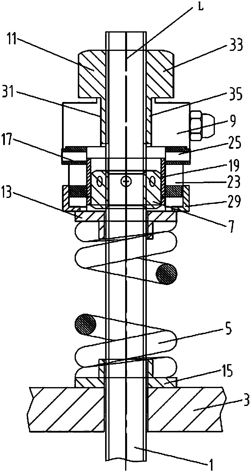
[0028] refer to figure 1 , an elevator suspension rope tension measurement and adjustment mechanism, including a screw 1, a rope seat 3, an elastic element 5, a lock nut 7, a pressure sensor 9 and an adjustment nut 11.

[0029] Above-mentioned screw rod 1, rope head seat 3 and elastic element 5 are the existing structures of the elevator, wherein the lower end of screw rod 1 is connected to the elevator suspension rope (not shown), the rope head seat 3 is threadedly set on the screw rod 1, and the elastic element 5 It is a compression spring, which is sleeved on the screw rod 1 and located above the rope end seat 3 . The upper and lower ends of the elastic element 5 are provided with upper and lower spring pads 13 , 15 sheathed on the screw rod 1 , wherein the lower spring pad 15 is arranged between the elastic element 5 and the rope end seat 3 .

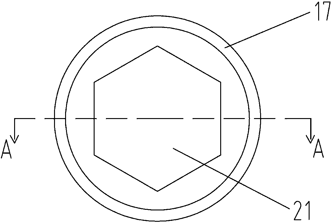
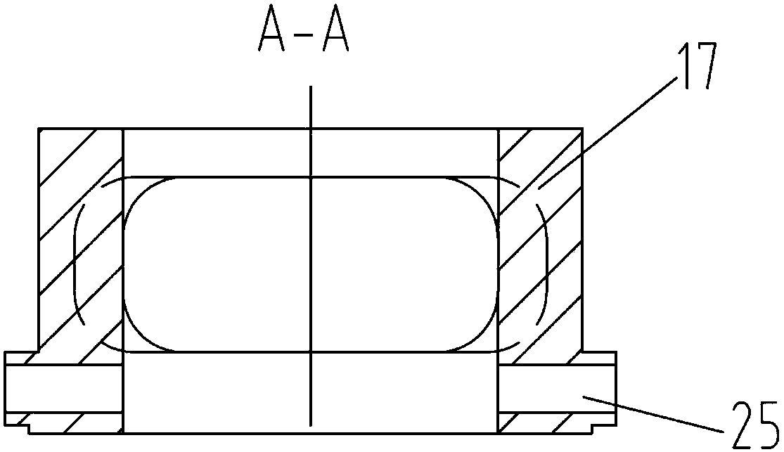
[0030] further reference figure 2 with Figure 5 , the lock nut 7 is threadedly connected to the screw rod 1 , and an adjuster...

Embodiment 2

[0035] further reference Figure 8 with Figure 9 Compared with Embodiment 1, the tension measurement and adjustment mechanism of this embodiment is only slightly different in shape from the regulator 40 and the regulator 17 of the first embodiment, so only the regulator 40 is explained and omitted. Description of the remaining components.

[0036]The above-mentioned regulator 40 is roughly in the shape of a hollow cylinder, and a section of arc edge is cut along its axial direction, thus forming a cylinder 42 , an irregular inner cavity 44 and a single adjustment window 46 . Likewise, its top end is provided with a plurality of adjustment holes 48 along its periphery. In this way, the adjuster 40 can also achieve the adjustment of the locking nut by opening an adjustment window 46 . Moreover, the adjuster 40 of this embodiment does not need to be sleeved down from the upper end of the screw rod 1 during assembly, and only needs to install the adjuster 40 from the side of t...


PUM


Abstract

The invention discloses a tension measurement and regulation mechanism for a lift suspension rope. The mechanism comprises a screw, an elastic component, a locknut and a pressure sensor, wherein the end of the screw is connected with the suspension rope, and the elastic component, the locknut and the pressure sensor are arranged on the screw in a sleeving mode in sequence. The tension measurement and regulation mechanism for the lift suspension rope further comprise a regulation nut which is arranged at the end of the screw in a sleeving mode and connected with the screw in a threaded mode, the regulation nut makes contact with the pressure sensor directly and can press the pressure sensor in the mode of uniform pressure, and the regulation nut is provided with a guide portion which is located between the screw and the pressure sensor. According to the tension measurement and regulation mechanism for the lift suspension rope, the special regulation nut is arranged, therefore, not only is output pressure of the pressure sensor more precise, but also the whole structure of the mechanism is simpler, and the production cost is more economical.

Description

technical field [0001] The invention relates to an elevator suspension rope tension measuring and adjusting mechanism. Background technique [0002] As we all know, the suspension ropes of the elevator car will have uneven tension after being used for a period of time, and this uneven tension will have a great impact on the performance of the elevator, the life of the suspension ropes and the sheave, such as It will cause the surface pressure of the rope groove of the traction wheel to be uneven. If the force is concentrated in a few rope grooves, the wear of the rope groove will be intensified; secondly, the elastic elongation of the suspension rope will be different due to the stress. , causing part of the suspension rope to change from static friction to sliding friction in the rope groove, thereby swallowing the material, affecting the comfort of the elevator car, and accelerating the scrapping speed of the suspension rope and traction sheave. Therefore, elevator manufa...

Claims


Application Information

Patent Timeline
Patent Type & Authority Patents(China)
IPC IPC(8): B66B7/10B66B5/00
CPCB66B5/0006B66B7/10
Inventor 李军
Owner SUZHOU BALANCE ELEVATOR TECH CO LTD
Why Eureka
Try Eureka