A valve seat ring for an alternative fuel engine

A valve seat ring and alternative fuel technology, used in engine components, turbines, mechanical equipment, etc., can solve the problems of fuel corrosion and wear, engine jitter, poor lubrication conditions, etc., to increase self-lubrication, improve wear resistance, reduce wear effect

Active Publication Date: 2017-01-18
CHERY AUTOMOBILE CO LTD
View PDF7 Cites 2 Cited by
  • Summary
  • Abstract
  • Description
  • Claims
  • Application Information

AI Technical Summary

Problems solved by technology

[0003] The use of alternative fuels is more severe for the engine valve seat. On the one hand, there is no cooling effect caused by the latent heat of gasoline, so the temperature of the valve seat is relatively high. Second, there is no colloidal component in the fuel that can act as a lubricant. , the lubrication condition is poor, and the third is the corrosion and wear caused by the fuel. The valve seat is easy to cause the wear of the valve seat under the above-mentioned environmental conditions, and it will also cause abnormal wear and cracking of the matching valve, resulting in air leakage of the valve, which in turn causes engine jitter, Fault phenomena such as poor cold start cause customer complaints and bring bad influence on the company's reputation
[0004] The existing alternative fuel valve seat material is a copper infiltrated material, the purpose is to increase the thermal conductivity of the valve seat by adding copper elements, but the working environment between the valve and the valve seat of the alternative fuel engine is worse than that of ordinary fuel, Especially under poor lubrication conditions, copper is easy to produce plastic flow under dry wear conditions, causing the valve seat material to adhere to the valve sealing surface, which will aggravate the wear between the valve and the valve seat, and then cause the gap between the valve and the valve seat. seal failure
In addition, the content of hard particles in the existing alternative fuel valve seat materials is generally about 20%. The low content of hard particles makes it difficult to meet the requirements for wear resistance when using natural gas and other fuels.

Method used


Image

  • A valve seat ring for an alternative fuel engine
  • A valve seat ring for an alternative fuel engine
  • A valve seat ring for an alternative fuel engine

Examples


Embodiment 1

[0024] The valve seat ring of an alternative fuel engine, its chemical composition (weight percentage) is: C content 1%, Si content 0.9%, Mn content 0.5%, S content 0.7%, Ni content 6%, Cr content 5%, Mo content 12 %, Co content 23%, balance Fe.

[0025] The valve seat ring adopts the processing method of powder metallurgy in a vacuum environment, and adopts two pressing and two sintering manufacturing processes in the processing process.

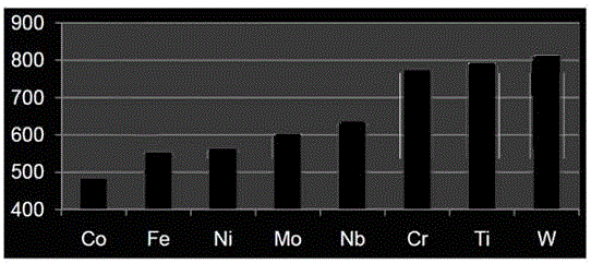
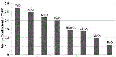
[0026] In the present invention, in order to improve the wear resistance and self-lubricating property of the valve seat ring material, the type of hard particles is improved and the content of hard particles is increased. The hard particle material is changed from the existing Cr-W-C system to have high Co-Mo-Cr series materials with high strength and lubricating properties. Compared with Cr-W-C series, Co-Mo-Cr series hard particles have a smaller dynamic friction coefficient and better self-lubricating properties, such as figure 1 The i...


PUM


Abstract

The invention relates to a valve seat ring for an alternative fuel engine. The valve seat ring comprises the following chemical components (weight percent): 0.8% -1.2% of C, 0.8% -1.2% of Si, 0. 4% -0.7% of Mn, 0.6% -0.9% of S, 5% -7% of Ni, 4% -6% of Cr, 10% -15% of Mo, 22%-27 % of Co, and the balance of Fe. The valve seat ring is machined by a powder metallurgy method in a vacuum environment, and the production process of two-time pressing and two-time sintering is adopted in the machining process. The valve seat ring has high abrasion resistance, high heat resistance and high corrosion resistance, the good matching of the valve seat ring and a valve is also ensured, and the high-strength valve seat ring material has good machinability, and the excessive machining cost cannot be caused. The content of hard particles reaches about 45%, and the high-strength valve seat ring can meet the requirements of various alternative fuels.

Description

technical field [0001] The invention belongs to the technical field of automobile engines and relates to a valve seat ring of an alternative fuel engine. Background technique [0002] In recent years, due to air pollution and lack of oil resources, it is required to continuously reduce harmful emissions from motor vehicles and increase the use of alternative fuels. Therefore, many countries are using alternative fuels to replace gasoline and diesel fuels. Currently, alternative fuels are widely used For natural gas, methanol, ethanol and other fuels, these alternative fuels are the development direction of renewable energy in the future, so it is necessary to develop high-strength valve seat rings to meet the use of alternative fuel engines. [0003] The use of alternative fuels is more severe for the engine valve seat. On the one hand, there is no cooling effect caused by the latent heat of gasoline, so the temperature of the valve seat is higher. Second, there is no colloi...

Claims


Application Information

Patent Timeline
Patent Type & Authority Patents(China)
IPC IPC(8): C22C38/60C22C30/00B22F5/00B22F3/16
Inventor 刘春红
Owner CHERY AUTOMOBILE CO LTD
Why Eureka
Try Eureka