Crankshaft brush plating platform

A technology of brush plating and crankshaft, applied in the direction of electrolysis process, electrolysis components, etc., can solve the problems of difficult quality assurance and low work efficiency, and achieve the effect of simple structure, high work efficiency and low manufacturing cost

Active Publication Date: 2015-05-20
GUANGXI UNIV
View PDF6 Cites 11 Cited by
  • Summary
  • Abstract
  • Description
  • Claims
  • Application Information

AI Technical Summary

Problems solved by technology

[0004] The purpose of the present invention is to provide a method to overcome the shortcomings of low wo

Method used


Image

  • Crankshaft brush plating platform
  • Crankshaft brush plating platform
  • Crankshaft brush plating platform

Examples


Embodiment Construction

[0027] The specific embodiments of the present invention will be described in detail below in conjunction with the accompanying drawings, but it should be understood that the protection scope of the present invention is not limited by the specific embodiments.

[0028] Unless expressly stated otherwise, throughout the specification and claims, the term "comprise" or variations thereof such as "includes" or "includes" and the like will be understood to include the stated elements or constituents, and not Other elements or other components are not excluded.

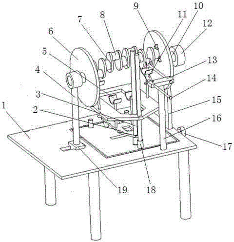
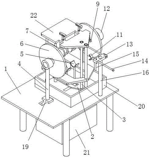
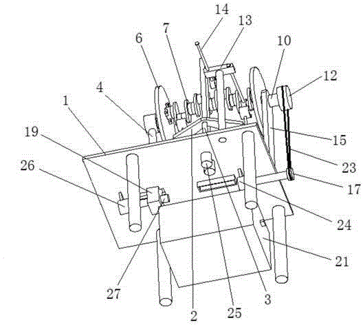
[0029] like Figure 1 to Figure 7 As shown, an embodiment according to a specific embodiment of the present invention is: a crankshaft electric brush plating platform, which includes: a workbench 1, a fixed support 15, a movable support 4, a rotating disk 6, a chuck 9 and a brush 5, wherein :

[0030] like figure 1 As shown, the workbench 1 is erected on the ground by four supporting legs. The fixed bracket 15 is fixedl...


PUM


Abstract

The invention discloses a crankshaft brush plating platform which comprises a worktable, a fixing bracket, a moving bracket, rotating discs, chucks and brushes, wherein the fixing bracket is fixedly arranged on the right side of the worktable; the moving bracket is arranged on the left side of the worktable in a left-right sliding mode and is driven to slide by virtue of a moving device; the two rotating discs are respectively erected at the upper ends of the fixing bracket and the moving bracket in a rotatable mode; the rotating disc arranged on the fixing bracket is driven by a rotating device; the two chucks are respectively and eccentrically arranged on the two rotating discs; the brushes are in the shape of arcs which correspond to the cranks; multiple pairs of brushes are respectively arranged on the worktable by virtue of lifting devices; and after the crankshaft is arranged on the two rotating discs, the multiple pairs of brushes respectively correspond to the multiple pairs of cranks of the crankshaft. According to the platform disclosed by the invention, the crankshaft can be subjected to mechanical brushing electroplating, the crankshaft is conveniently mounted and positioned, the working efficiency is high, and the brushing electroplating quality of the crankshaft can be guaranteed.

Description

technical field [0001] The invention relates to the field of electric brush plating, in particular to a crankshaft electric brush plating platform. Background technique [0002] The crankshaft is an important part of the engine. There are several pairs of crank throws symmetrically arranged on the crankshaft. These crank throws are respectively connected with several connecting rods, and several connecting rods are respectively connected with the pistons in several cylinders. Through the connecting rods, the Turn the up and down linear reciprocating motion of the piston into the cyclic rotation of the crankshaft to realize the output of power. Due to the frequent relative movement between the crankshaft and the connecting rod during the working process, the wear of the crankshaft is one of the main forms of crankshaft damage. In order to reduce costs and improve resource utilization, it is necessary to brush-plate worn crankshafts to repair the crankshaft for remanufacturin...

Claims


Application Information

Patent Timeline
IPC IPC(8): C25D5/06C25D7/00C25D17/00
CPCC25D5/06C25D7/00C25D17/00
Inventor 黄伟辛小刚段月星张章徐敏敏张亚丽王永康
Owner GUANGXI UNIV
Why Eureka
Try Eureka