Device and method for closure construction of girder side span of cable-stayed bridge

A cable-stayed bridge and side span technology, applied in cable-stayed bridges, bridges, bridge forms, etc., can solve the problems of inability to achieve statically indeterminate locking, inability to overcome synchronous free expansion and contraction of cast-in-place sections, and high construction costs

Inactive Publication Date: 2015-05-20
THE 5TH ENG MBEC +1
View PDF5 Cites 9 Cited by
  • Summary
  • Abstract
  • Description
  • Claims
  • Application Information

AI Technical Summary

Problems solved by technology

[0003] During the construction of the cast-in-place section of the main girder of the cable-stayed bridge with high piers and large spans, it is difficult to erect steel pipe supports or frames at the construction site, and super static locking cannot be achieved. The segment and the poured main girder body can be freely expanded and contracted synchronously
[0004] At the same time, when the external temperature changes greatly, the length of the cable-stayed cables of the cable-stayed bridge will change due to thermal expansion and contraction. Causes cracks at the joints between the beam body and the cast-in-place section, which needs to be repaired, and the construction cost is high

Method used


Image

  • Device and method for closure construction of girder side span of cable-stayed bridge
  • Device and method for closure construction of girder side span of cable-stayed bridge
  • Device and method for closure construction of girder side span of cable-stayed bridge

Examples


Embodiment Construction

[0031] Embodiments of the present invention will be described in further detail below in conjunction with the accompanying drawings.

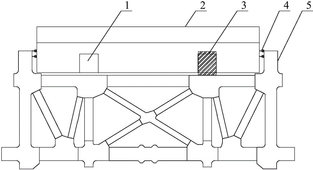
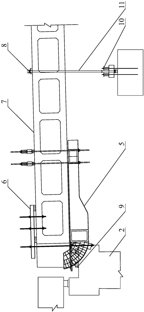
[0032] see figure 1 with figure 2 As shown, the embodiment of the present invention provides a device and method for closing the side spans of the main girder of a cable-stayed bridge. The cantilever beam 6 at the top of the beam 7, the stay cable hanging basket 5 arranged at the bottom of the poured main beam 7 and the down-down cable system arranged on the poured main beam 7, the side span closing section support pier 2 is located 7, the cantilever beam 6 is located above the pier top support system 9 and the guy rope hanging basket 5.

[0033] The lanyard hanging basket 5 comprises two arc heads, and the outside of each arc head is welded with a lateral positioning fixed pulley 4, and the lateral positioning fixed pulley 4 is fixed on the outside of the side span closing section buttress 2.

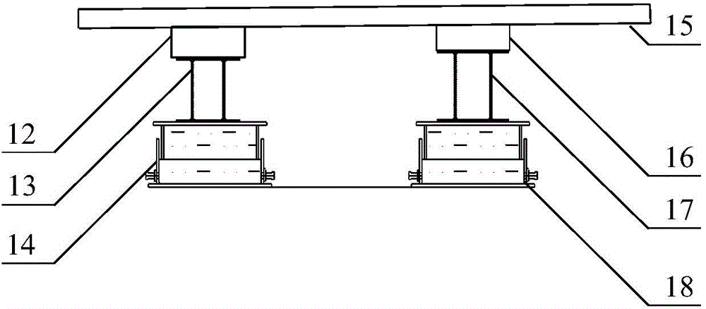
[0034] join image 3 with Figure 4 As show...


PUM


Abstract

The invention discloses a device and a method for closure construction of a girder side span of a cable-stayed bridge and relates to the field of construction of cable-stayed bridges. The device comprises a cable drawing hanging basket, a pier top support system and a cantilever outrigger, wherein the cable drawing hanging basket is arranged at the bottom of a cast girder, the pier top support system is arranged at the top of a side span closure section pier, and the cantilever outrigger is arranged at the top of the cast girder and above the pier top support system and the cable drawing hanging basket. The cable drawing hanging basket comprises two arc-shaped heads, and a transverse limit fixed pulley is welded on the outer side of each arc-shaped head and fixed on the outer side of the side span closure pier. The pier top support system comprises a first support, a second support, a plurality of first sand boxes and second sand boxes at the top of the side span closure section pier, and the outer portions of the first support and the second support are sleeved with support cover plates. The cast-in-situ section and the cast girder body are freely and synchronously telescopic, and construction cost is reduced.

Description

technical field [0001] The invention relates to the construction field of cable-stayed bridges, in particular to a device and method for closing side spans of main girders of cable-stayed bridges. Background technique [0002] When the side spans of the main girder of a conventional cable-stayed bridge are closed, the cast-in-place section and the closing section are usually set with reference to the continuous steel structure construction method. After the counterweight, the cast-in-place section and the side spans are fixed with a rigid framework, so that the main beam is in a statically indeterminate state, and then the side spans are closed. [0003] During the construction of the cast-in-place section of the main girder of the cable-stayed bridge with high piers and large spans, it is difficult to erect steel pipe supports or frames at the construction site, and super static locking cannot be achieved. The segments are free to expand and contract synchronously with the...

Claims


Application Information

Patent Timeline
Patent Type & Authority Applications(China)
IPC IPC(8): E01D21/10
CPCE01D21/10E01D11/04
Inventor 张海燕江雄吕新阳郑杰杨林保王泽岸王伟李磊王超孙铮
Owner THE 5TH ENG MBEC
Why Eureka
Try Eureka