Petroleum drilling machine tower-shaped derrick sleeving mounting method
A technology of tower-shaped derrick and installation method, which is applied in the direction of drilling equipment, earthwork drilling and production, support devices, etc., can solve the problems of high risk of installation personnel, unscientific installation methods, long installation time, etc., to reduce the risk of falling from high altitude, The effect of saving installation time and reducing installation workload
- Summary
- Abstract
- Description
- Claims
- Application Information
AI Technical Summary
Problems solved by technology
Method used
Image

Examples
Embodiment Construction
[0023] The present invention will be described in detail below in conjunction with the accompanying drawings and specific embodiments.
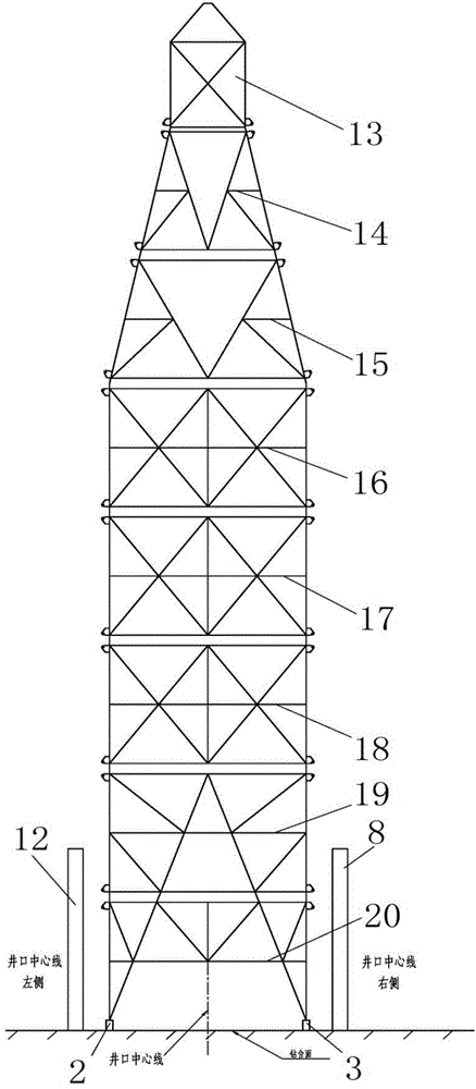
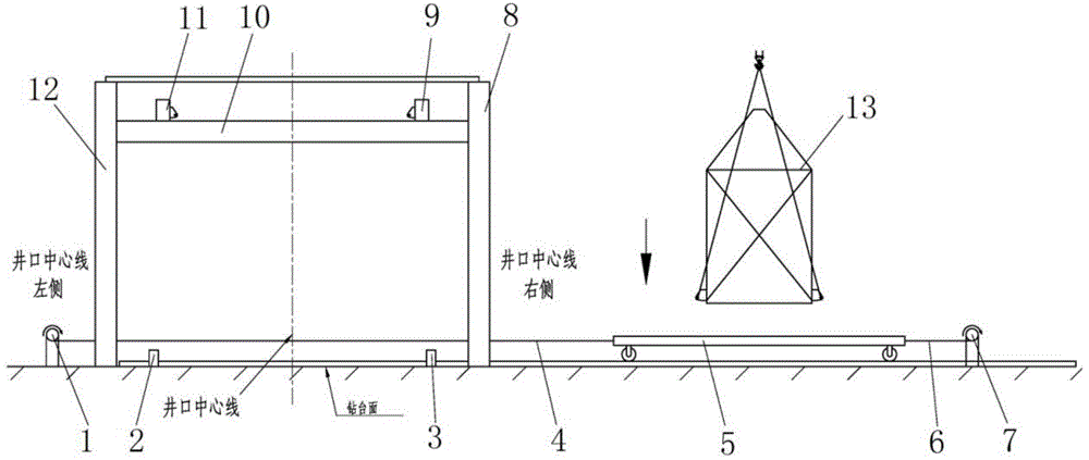
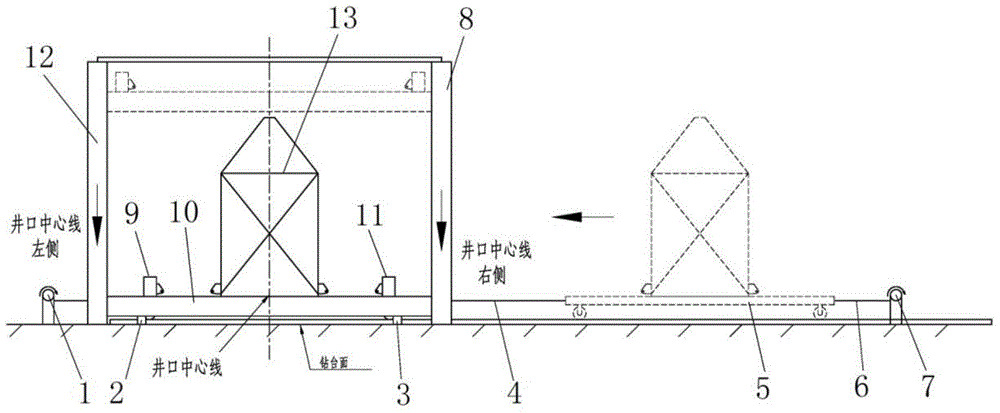
[0024] refer to figure 1 , figure 2 , the object of implementation of the suit installation method of the present invention, the structure of the tower derrick embodiment is that it is divided into 8 sections in the order from top to bottom, which are respectively: crown block and crown frame 13, derrick upper section 14, derrick The second section 15, the third section 16 of the derrick, the fourth section 17 of the derrick, the fifth section 18 of the derrick, the sixth section 19 of the derrick, and the lower section 20 of the derrick. ( figure 1 Among them, there is a section of downward short line segment (except the sky frame 13 lower ends) at the left and right ends of each section of the bottom horizontal line, and the lower end point of this short line segment is exactly the connection position (with the horizontal line on the top...
PUM
 Abstract
Description
Claims
Application Information
 - R&D
- Intellectual Property
- Life Sciences
- Materials
- Tech Scout
- Unparalleled Data Quality
- Higher Quality Content
- 60% Fewer Hallucinations
Browse by: Latest US Patents, China's latest patents, Technical Efficacy Thesaurus, Application Domain, Technology Topic, Popular Technical Reports.
© 2025 PatSnap. All rights reserved.Legal|Privacy policy|Modern Slavery Act Transparency Statement|Sitemap|About US| Contact US: help@patsnap.com