
Proportional hydraulic control valve group and metal belt continuously variable transmission

A technology of continuously variable transmission and hydraulic control valve, which is applied in transmission control, components with teeth, belts/chains/gears, etc. It can solve the problem of poor filtration accuracy control, pressure stability, large valve plate size requirements, and high precision requirements. Problems, to achieve the effect of strong anti-pollution ability, less assembly size requirements, and low precision requirements

Active Publication Date: 2016-10-05
泸州容大智能变速器有限公司
View PDF6 Cites 0 Cited by
  • Summary
  • Abstract
  • Description
  • Claims
  • Application Information

AI Technical Summary

Problems solved by technology

[0006] The invention provides a proportional hydraulic control valve group for a metal belt continuously variable transmission and the metal belt continuously variable transmission to solve the direct problem of the existing hydraulic system through the high power proportional solenoid valve integrated by the pilot valve and the slide valve. Control pulley, output pulley oil cylinder pressure, valve plate size requirements, high precision requirements, high processing cost, poor filtration accuracy and control pressure stability technical problems

Method used


Image

  • Proportional hydraulic control valve group and metal belt continuously variable transmission
  • Proportional hydraulic control valve group and metal belt continuously variable transmission
  • Proportional hydraulic control valve group and metal belt continuously variable transmission

Examples


Embodiment Construction

[0027] The embodiments of the present invention will be described in detail below with reference to the accompanying drawings, but the present invention can be implemented in various ways defined and covered.

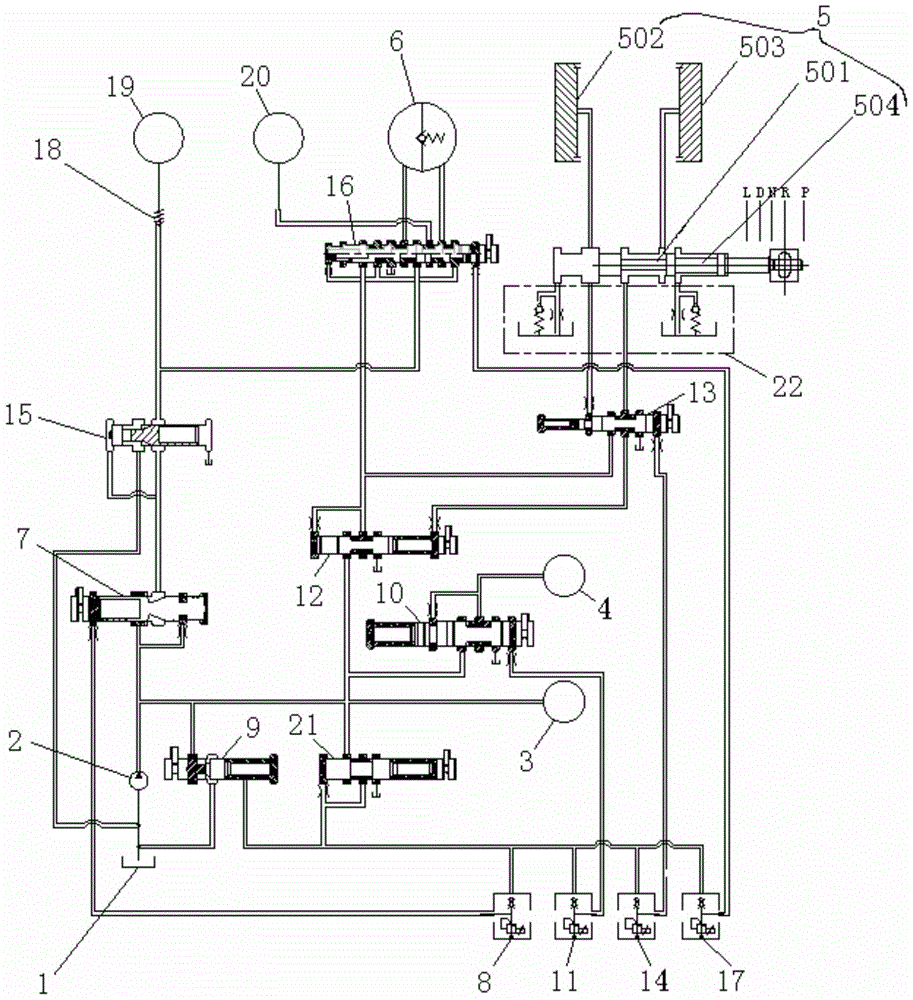
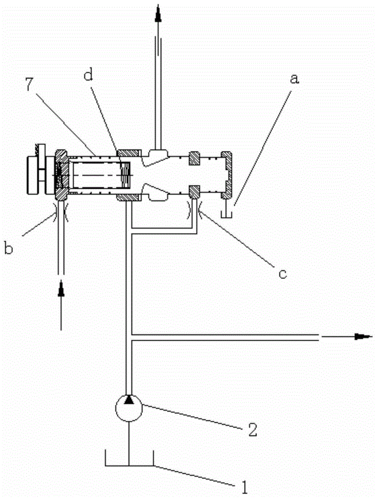
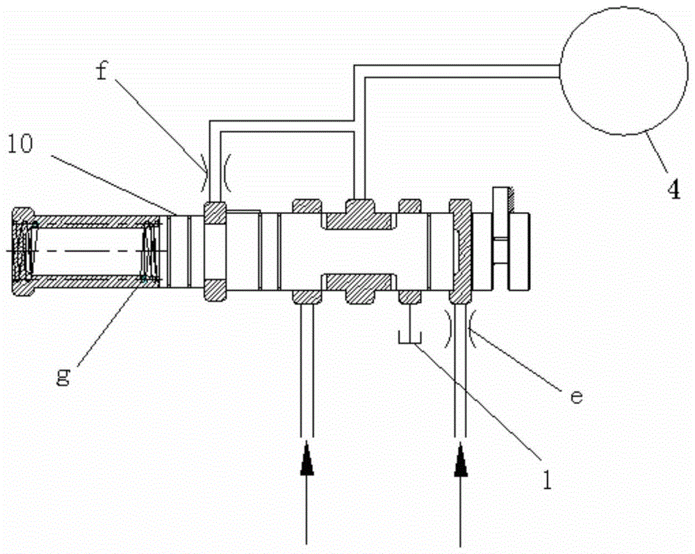
[0028] figure 1 It is a structural schematic diagram of a proportional hydraulic control valve group for a metal belt continuously variable transmission according to a preferred embodiment of the present invention; figure 2 It is a structural schematic diagram of a passive slide valve in a preferred embodiment of the present invention; image 3 It is a structural schematic diagram of an active slide valve in a preferred embodiment of the present invention; Figure 4 It is a structural schematic diagram of the clutch hydraulic part of the preferred embodiment of the present invention; Figure 5 It is a structural schematic diagram of the backstop impact buffer device in the preferred embodiment of the present invention.

[0029] Such as figure 1 with figure 2As sh...


PUM


Abstract

The invention discloses a proportional hydraulic control valve set and a metal-belt type stepless transmission. The proportional hydraulic control valve set used for the metal-belt type stepless transmission comprises an integrated oil tank, an output belt wheel cylinder, an input belt wheel cylinder, a clutch cylinder and an oil pump, the integrated oil tank is used for storing oil, the output belt wheel cylinder is used for delivering the oil in the integrated tank to the stepless transmission, the oil pump delivers the oil to a torque converter, the input end of the oil pump is communicated with the integrated oil tank, the oil input end of the output belt wheel cylinder is communicated with the output end of the oil pump, a passive slide valve used for controlling pressure of the oil pumped into the output belt wheel cylinder and a passive pilot solenoid valve used for outputting pilot pressure to the passive slide valve so as to control pressure of the oil delivered from the passive slide valve to the output belt wheel cylinder are arranged at the oil input end of the output belt wheel cylinder, and the oil output end of the oil pump is communicated with the inlet end of the passive slide valve; the maximum pressure outputted by the passive pilot solenoid valve is smaller than that controlled by the passive slide valve. The pressure of the output belt wheel cylinder is controlled.

Description

technical field [0001] The invention relates to the field of hydraulic control mechanisms of continuously variable transmissions, in particular to a proportional hydraulic control valve group for metal-belt continuously variable transmissions. In addition, the present invention also relates to a metal-belt continuously variable transmission comprising the above-mentioned proportional hydraulic control valve group for the metal-belt continuously variable transmission. Background technique [0002] As a kind of automatic transmission, the metal belt continuously variable transmission has been widely used in the market. As the key assembly connecting the TCU (transmission electronic control unit) and the mechanical actuators of the transmission—the hydraulic system assembly is constantly changing with the continuous development of solenoid valve technology. [0003] Existing hydraulic systems usually use high-power proportional solenoid valves to directly control the input pul...

Claims


Application Information

Patent Timeline
Patent Type & Authority Patents(China)
IPC IPC(8): F16H61/662F16H61/38
CPCF16H61/0025F16H61/0265F16H61/6624F16H2061/6604
Inventor 罗威康明高帅吴付佑龙亚彬邓玉林
Owner 泸州容大智能变速器有限公司
Learn More