Thermal protection method of porous medium jetting support plate leading edge nose cone

A technology for injecting struts and porous media, which is applied in combustion methods, lighting and heating equipment, combustion chambers, etc., can solve problems such as high stagnation temperature, damage to injection struts, engine flameout, etc., and achieve rapid and stable combustion, Easy to ignite and burn, enhance the effect of fuel blending

Inactive Publication Date: 2015-05-20
TSINGHUA UNIV
View PDF7 Cites 18 Cited by
  • Summary
  • Abstract
  • Description
  • Claims
  • Application Information

AI Technical Summary

Problems solved by technology

In particular, the stagnation temperature at the nose cone at the front edge of the injection strut is extremely high, which can easily cause local ablation and cause damage to the injection strut, resulting in major safety issues such as engine flameout

Method used


Image

  • Thermal protection method of porous medium jetting support plate leading edge nose cone
  • Thermal protection method of porous medium jetting support plate leading edge nose cone
  • Thermal protection method of porous medium jetting support plate leading edge nose cone

Examples


Embodiment Construction

[0020] The present invention will be described in detail below in conjunction with the accompanying drawings and embodiments.

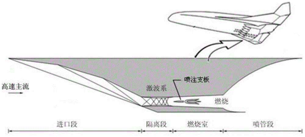
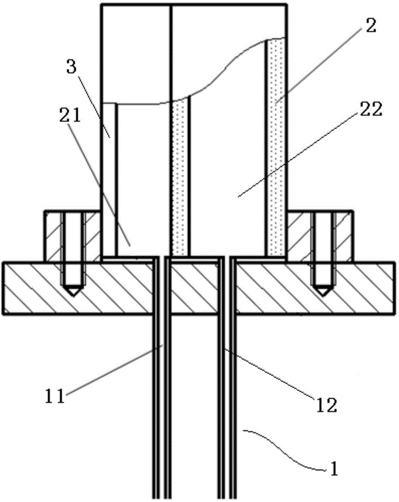
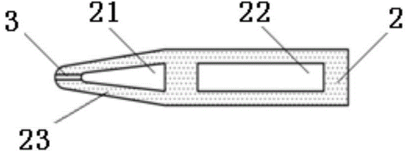
[0021] Such as figure 1 , figure 2 As shown, the fuel connected to the injection branch plate 2 by the fuel pipe 1 is controlled by the pump carried by the super-combustion engine itself and the valve arranged on the fuel channel. After reaching a certain pressure, it enters the injection branch plate 2 through the fuel pipe 1 , mixed with the high-speed air behind the shock wave system in the combustion chamber and then burned, the generated gas is ejected backward to provide power. The shape of the porous medium material used in the injection support plate 2 and the injection support plate 2 in the present invention is basically the same as that of the prior art, and the difference is that the structure, cooling method and oil injection method of the injection support plate 2 are used in the present invention. Improvements on. The difference bet...


PUM


Abstract

The invention relates to a thermal protection method of a porous medium jetting support plate leading edge nose cone. The thermal protection method comprises the following steps that firstly, a narrow seam is formed in the jetting support plate leading edge nose cone, a front cavity of a jetting support plate is communicated with one fuel pipe, and a back cavity of the jetting support plate is communicated with the other fuel pipe; secondly, most of low-temperature fuel is quickly sprayed out of the narrow seam through the fuel pipe arranged at the front cavity, and the rest part of fuel permeates to the surface of the front cavity in a sweating mode; thirdly, the fuel sprayed to the leading edge is collected through the narrow seam, and produced detached shock waves are pushed away from the leading edge nose cone; fourthly, a thick protection air film is formed at the leading edge nose cone through the fuel sprayed out of the narrow seam and under the action of high-speed main stream, the thick protection air film is fused with a compact air film formed on the surface of the jetting support plate in a sweating and cooling mode, and thermal protection for the jetting support plate is enhanced. According to the thermal protection method, due to the fact that the fuel is sprayed to the high-speed main stream through the narrow seam at the leading edge nose cone, the low-temperature fuel serves as coolant for reducing the temperature of the leading edge nose cone when sprayed out of the narrow seam, meanwhile the sprayed fuel can form the protection air film on the surface of the jetting support plate, and the protection air film can conduct effective thermal protection on the jetting support plate.

Description

technical field [0001] The invention relates to a thermal protection method for injection struts of scram engines, in particular to a thermal protection method for the nose cone of the front edge of porous media injection struts in high-temperature and high-speed airflow. Background technique [0002] In the scramjet combustion chamber, fuel and supersonic air are mixed and burned to obtain thrust so that the aircraft can fly at supersonic speed. However, because the fuel is injected into the supersonic airflow, the residence time of the fuel in the combustion chamber is only a few milliseconds, which may cause insufficient mixing and even lead to the occurrence of ignition failure problems. Therefore, the injection support plate is installed in the scramjet combustion chamber The fuel is directly injected into the core area of ​​the main flow through the injection support plate, which can effectively enhance the mixing between the fuel and the main flow and improve the comb...

Claims


Application Information

Patent Timeline
Patent Type & Authority Applications(China)
IPC IPC(8): F23R3/28
Inventor 姜培学黄干祝银海
Owner TSINGHUA UNIV
Why Eureka
Try Eureka